
Super-resolution optical recording medium, optical recording medium reproduction device, control method of optical recording medium reproduction device, control program for optical recording medium reproduction device, and computer-readable recording medium for storing the program

a super-resolution, optical recording medium technology, applied in the direction of optical recording/reproducing/erasing methods, recording signal processing, instruments, etc., can solve the problems of super-resolution medium not being able to reproduce, super-resolution medium being rejected as irreproducible medium, and normal medium being broken

Active Publication Date: 2010-08-19
SHARP KK
View PDF35 Cites 19 Cited by
  • Summary
  • Abstract
  • Description
  • Claims
  • Application Information

AI Technical Summary

Benefits of technology

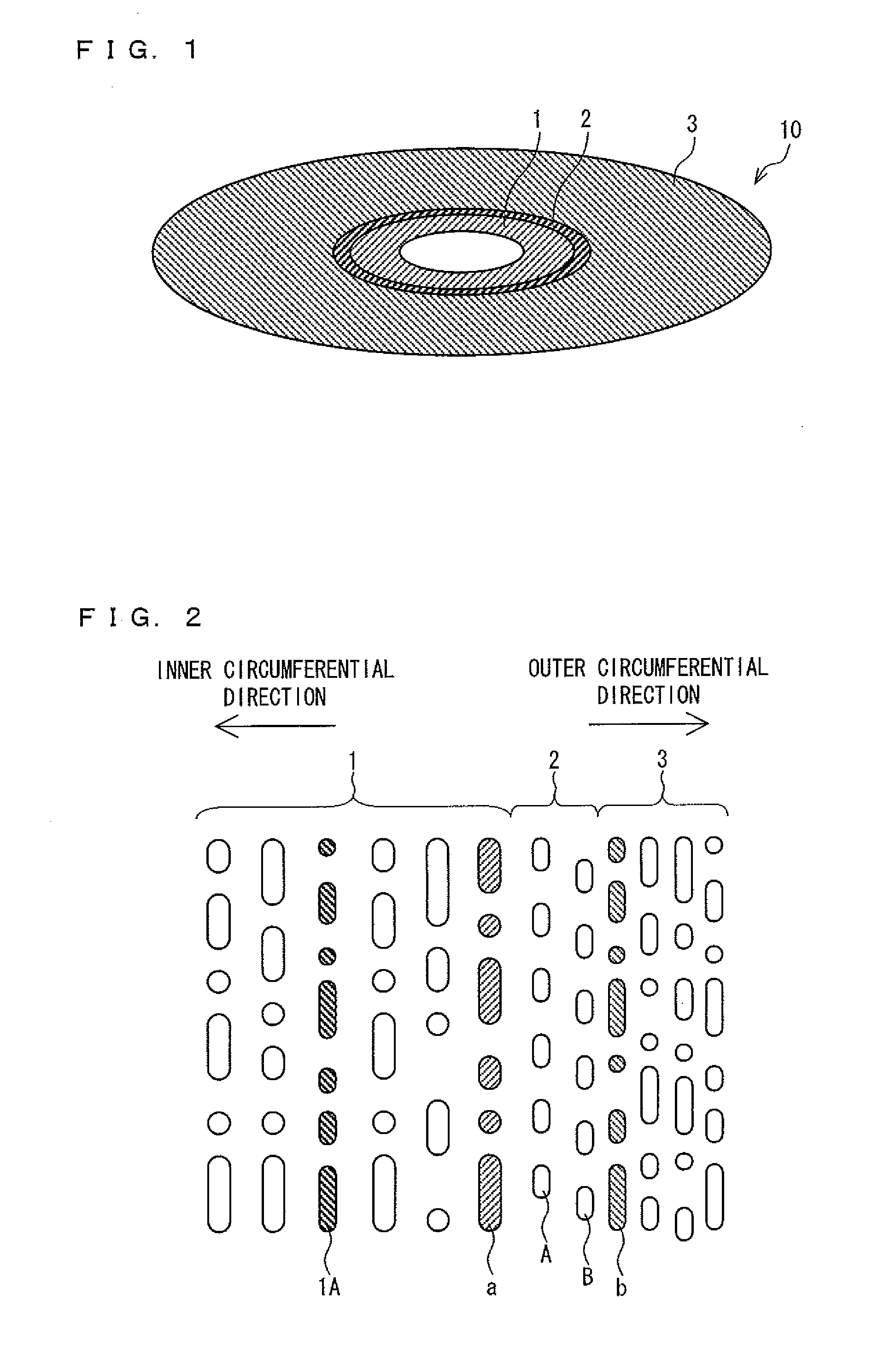
[0021]According to the arrangement, the medium identification information recorded on the first region is recorded with the use of a train of prepits which is constituted by prepits longer than the resolution limit of the optical system of the optical recording medium reproduction device, i.e., the medium identification information recorded on the first region is recorded in a similar manner to a normal optical recording medium. This allows the medium identification information to be reproduced with the use of a laser beam having power for a normal optical recording medium. Therefore, the optical recording medium reproduction device (i) irradiates a medium loaded into the optical recording medium reproduction device with a laser beam having power suitable for a normal optical recording medium so as to read out the medium identification information, and then (ii) determines, based on the medium identification information, whether the medium thus loaded is a normal optical recording medium or a super-resolution optical recording medium. Based on a result thus determined, the optical recording medium reproduction device can carry out processing in accordance with the medium thus loaded (can change, for example, the power of a laser beam in accordance with the medium thus loaded). This allows realization of a compatible reproduction device that is capable of reproducing both of a normal optical recording medium and the super-resolution optical recording medium.
[0047]As such, it is possible to realize a super-resolution optical recording medium in which a region on which medium identification information is recorded and a region on which content information is recorded are different in track pitch and in which a reproduction error hardly occurs when reproduction shifts from the region on which the medium identification information is recorded to the region on which the content information is recorded.

Problems solved by technology

Therefore, a super-resolution medium cannot be reproduced with the use of a reproduction device which is designed to reproduce a normal medium since such a reproduction device emits a laser beam having low power.
As a result, such a super-resolution medium is rejected as an irreproducible medium.
Meanwhile, in a case where a normal medium is mistakenly loaded into a reproduction device which is designed to reproduce a super-resolution medium, such a normal medium may be broken due to heat since such a reproduction device emits a laser beam having high power.

Method used


Image

  • Super-resolution optical recording medium, optical recording medium reproduction device, control method of optical recording medium reproduction device, control program for optical recording medium reproduction device, and computer-readable recording medium for storing the program
  • Super-resolution optical recording medium, optical recording medium reproduction device, control method of optical recording medium reproduction device, control program for optical recording medium reproduction device, and computer-readable recording medium for storing the program
  • Super-resolution optical recording medium, optical recording medium reproduction device, control method of optical recording medium reproduction device, control program for optical recording medium reproduction device, and computer-readable recording medium for storing the program

Examples


embodiment 1

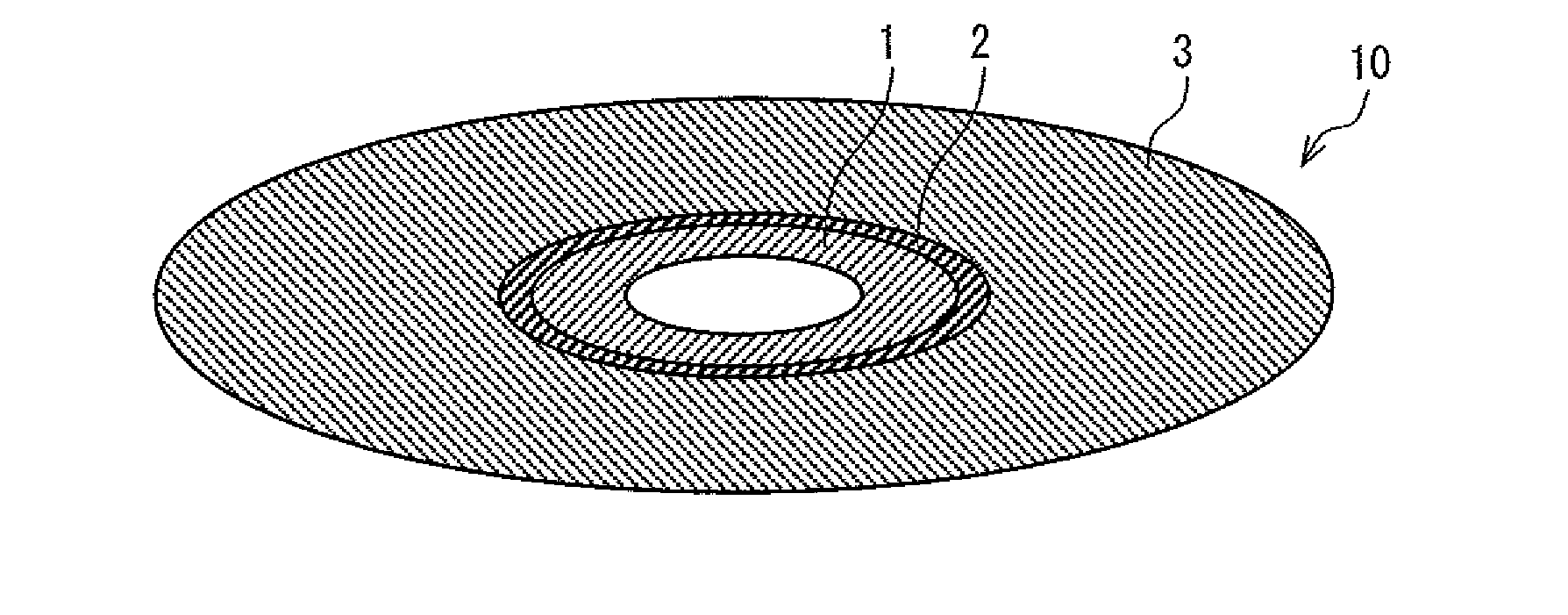
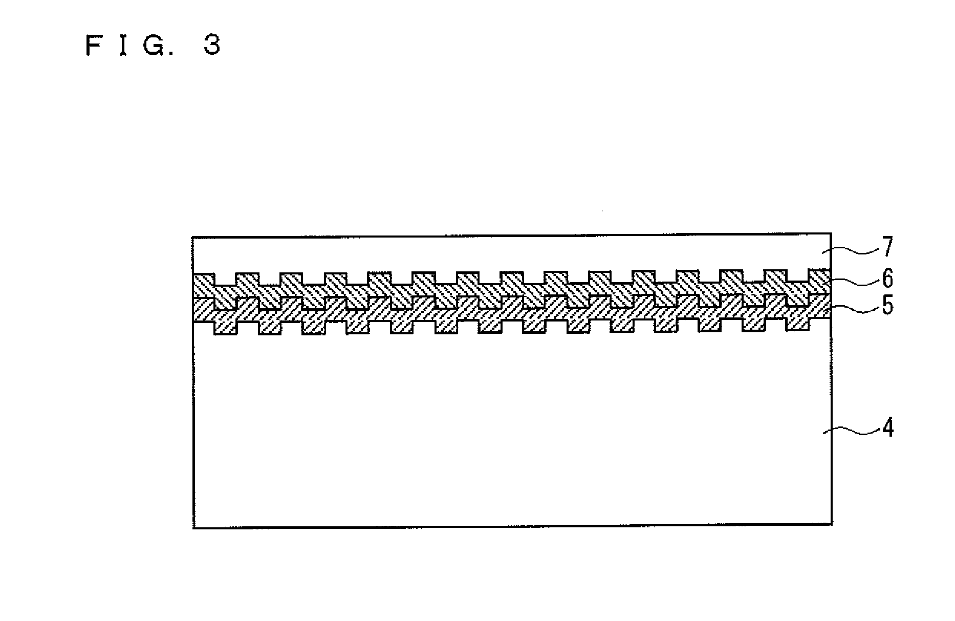
[0077]An embodiment of a super-resolution optical recording medium of the present invention is described below with reference to FIGS. 1 through 3. A super-resolution optical recording medium (hereinafter referred to as “super-resolution medium”) 10 of the present embodiment is a reproduction-only medium, and is a super-resolution medium having a cross-sectional structure of a BD (Blu-ray Disc) type. According to the present embodiment, an optical system of a reproduction device has the following particulars: a laser wavelength is 405 nm, a numerical aperture of a converging lens is 0.85, and a resolution limit is 119 nm. Note that the characteristics of each semiconductor laser, which is operated in conformity with a standard such as a BD standard, vary from semiconductor laser to semiconductor laser due to their manufacturing process. On this account, in a case where a laser beam is described herein as having a laser wavelength of 405 nm, it means that the laser beam has a laser w...

embodiment 2

[0114]Another embodiment of a super-resolution medium of the present invention is described below with reference to FIGS. 4 and 5. For convenience of description, constituents which have identical functions to those of the Embodiment 1 are given identical reference numerals, and are not explained repeatedly. Basically, the following description deals with differences from the super-resolution medium 10 of the Embodiment 1.

[0115]FIG. 4 is a view illustrating an external appearance of a super-resolution medium 10a of the present embodiment.

[0116]The super-resolution medium 10a includes a medium information region (first region) 1a on which medium information is recorded, a content region (second region) 3a on which content information such as video or software is recorded, and a blank region 2a provided between the medium information region 1a and the content region 3a.

[0117]FIG. 5 is an enlarged view of a vicinity of the blank region 2a.

[0118]The medium information region 1a is dif...

embodiment 3

[0133]Another embodiment of a super-resolution medium of the present invention is described below with reference to FIG. 6. For convenience of description, constituents which have identical functions to those of the Embodiment 2 are given identical reference numerals, and are not explained repeatedly. Basically, the following description deals with differences from the super-resolution medium 10a of the Embodiment 2.

[0134]FIG. 6 is an enlarged view of a vicinity of a blank region 2b of a super-resolution medium 10b of the present embodiment.

[0135]The medium information region 1b is different from the medium information region 1a of the super-resolution medium 10a in that blank power information indicative of power of a laser beam with which the blank region 2b is irradiated is additionally recorded. The reproduction device reproduces the blank power information so as to recognize power of a laser beam suitable for blank region 2b. Note that the laser beam power suitable for the blan...


PUM

PropertyMeasurementUnit
laser wavelengthaaaaaaaaaa
lengthaaaaaaaaaa

Abstract

A super-resolution optical recording medium (10) of the present invention includes: a medium information region (1) on which medium identification information is recorded; a content region (3) on which content information is recorded; and a blank region (2) provided between the medium information region (1) and the content region (3) and in which at least two tracks are provided so as to connect a train of prepits in the medium information region (1) and a train of prepits in the content region (3). No information is recorded on the blank region (2). With this arrangement, the present invention provides a super-resolution optical recording medium in which a region on which medium identification information is recorded and a region on which content information is recorded are different in track pitch and in which a reproduction error hardly occurs when reproduction shifts from the region on which the medium identification information is recorded to the region on which the content information is recorded.

Description

TECHNICAL FIELD[0001]The present invention relates to a super-resolution optical recording medium on which information is recorded with the use of a train of prepits including prepits shorter than a resolution limit of an optical system of a reproduction device or a train of recording marks including recording marks shorter than the resolution limit of the optical system of the reproduction device, the information being reproduced with the use of a super-resolution technique. The present invention especially relates to (i) a super-resolution optical recording medium (a) which can be reproduced by a reproduction device which is also capable of reproducing a normal optical recording medium on which information is recorded with the use of a train of prepits which is constituted by prepits longer than the resolution limit of the optical system of the reproduction device and (b) in which a region where content information is recorded has a small track pitch so that high recording density...

Claims


Application Information

Patent Timeline
Patent Type & Authority Applications(United States)
IPC IPC(8): G11B19/00G11B7/24G11B7/24097
CPCG11B7/0053G11B7/00745G11B7/007G11B7/24091G11B7/24
Inventor SAKAI, TOSHIHIKOYAMADA, HIROHISAYAMAMOTO, MASAKIHARADA, YASUHIROMORI, GOTAJIMA, HIDEHARUTAKAMORI, NOBUYUKI
Owner SHARP KK
Learn More