Fan blade Anti-fretting insert

a technology of inserts and blades, applied in the direction of marine propulsion, liquid fuel engines, vessels, etc., can solve the problems of reducing the life of parts, adding weight, reducing the stiffness of dovetails, and causing wear and tear. the effect of preventing wear

Active Publication Date: 2010-08-19
PRATT & WHITNEY CANADA CORP
View PDF19 Cites 8 Cited by
  • Summary
  • Abstract
  • Description
  • Claims
  • Application Information

AI Technical Summary

Benefits of technology

[0003]According to a general aspect, there is provided a fan blade anti-fretting arrangement to prevent wear between a root portion of a fan blade and a root slot of a rotor fan hub of a turbo fan engine, the anti-fretting arrangement comprising a U-shaped insert member formed of a composite spring material having a memory, said insert member defining a bottom wall portion abutting an outer surface portion of the rotor fan hub between adjacent fan blades and opposed side wall portions formed integral with said bottom wall portion, said side wall portions being dimensioned to abut at an upper end thereof against a platform connection of the adjacent fan blades, said insert member being dimensioned to exert a pushing force against the connection platform of the adjacent fan blades and a pulling force on the root portion to prevent rocking of the root portion in the root slot at low rotational speeds.
[0004]According to a still further broad general aspect, there is provided a method of preventing wear between a root portion of a fan blade and a root slot of a rotor fan hub of a turbofan engine, said method comprising the steps of: providing an insert member formed of composite spring material having a memory, said insert member having a bottom wall portion and opposed side wall portions; positioning said insert member in a gap formed between root portions of adjacent fan blades with said bottom wall portion abutting an outer surface portion of said rotor fan hub in said gap and said opposed wall portions abutting at an upper end thereof against a platform connection of said adjacent fan blades; applying a pushing force against said platform connection to result in a pulling force on said root portion to prevent rocking of said root portion in said root slot at low rotational speeds of said rotor fan hub.

Problems solved by technology

This wear occurs usually at low speeds (e.g. wind milling) wherein the root section experiences movement within the blade root slot.
However, this adds weight and reduces dovetail stiffness.
When the fan is turned by wind action with the engine off, the fan blade does not cause sufficient centrifugal loading to stop the rocking of the fan blade root in the root slot resulting in fretting of the components thereby reducing the life of the parts.

Method used


Image

  • Fan blade Anti-fretting insert
  • Fan blade Anti-fretting insert
  • Fan blade Anti-fretting insert

Examples


Embodiment Construction

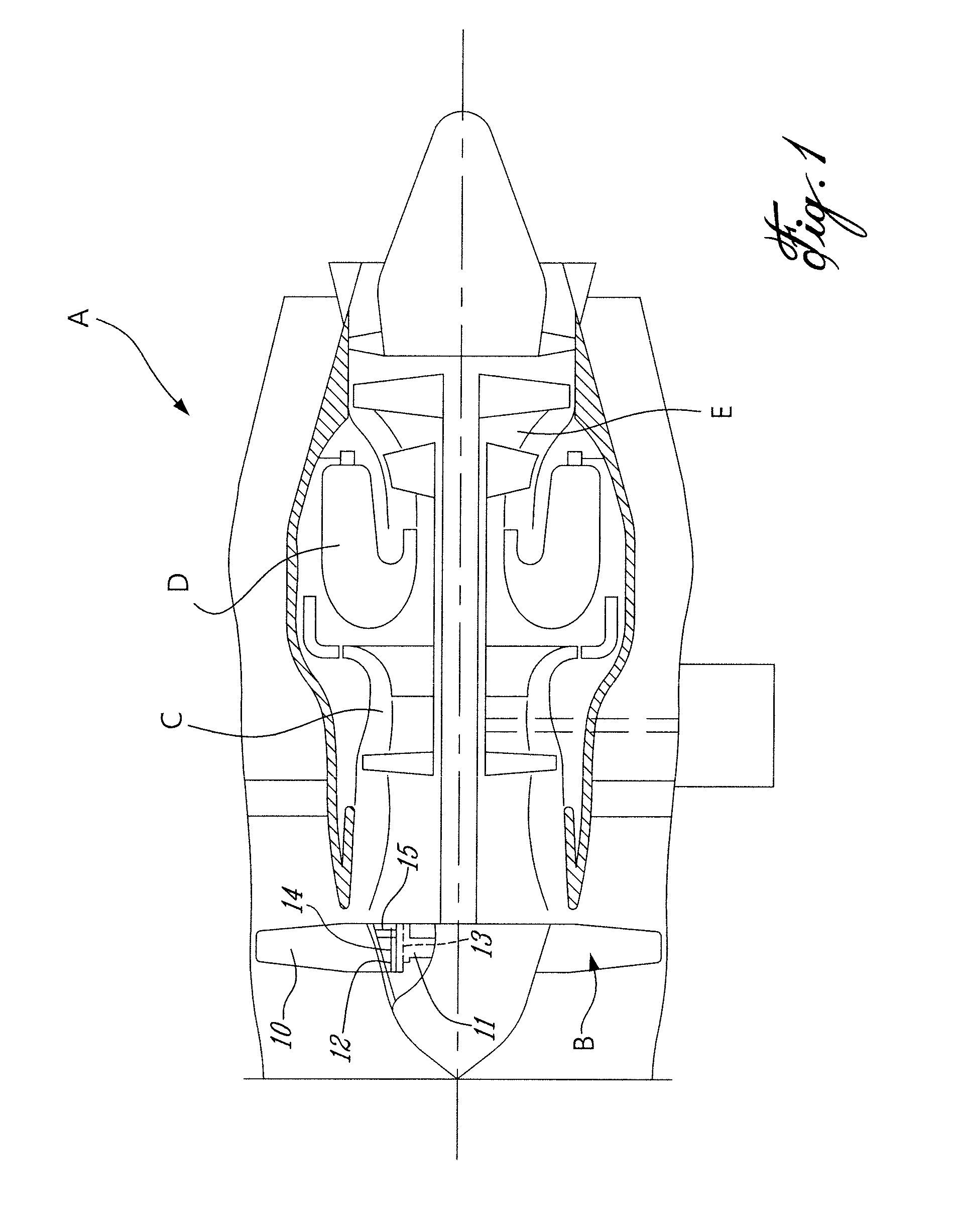
[0011]FIG. 1 illustrates a turbo fan gas turbine engine A of a type preferably provided for use in subsonic flight, and generally comprising in serial flow communication a fan section B through which ambient air is propelled, a multistage compressor C for pressurizing the air, a combustor D in which the compressed air is mixed with fuel and ignited for generating an annular stream of hot combustion gases, and a turbine section E for extracting energy from the combustion gases.

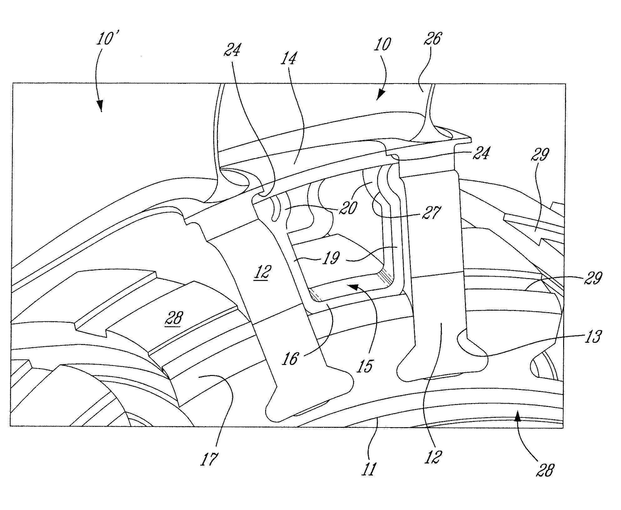
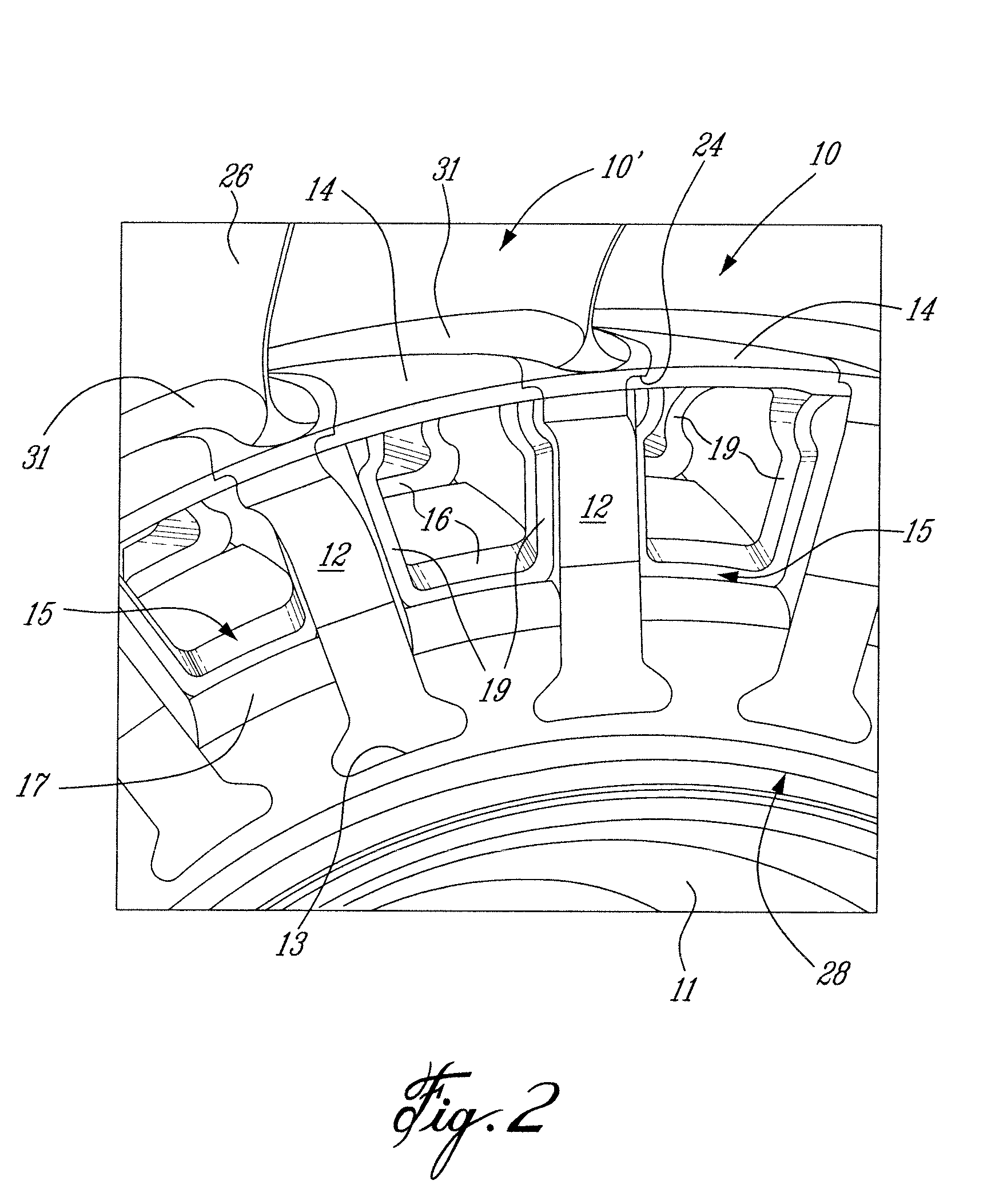
[0012]As herein shown, the fan blade section B is comprised of a plurality of fan blades 10 secured about a rotor fan hub 11. Each fan blade 10 has a root section 12 depending from the undersurface of a fan blade platform 31 (see FIGS. 2, 3 and 4). The root section 12 of each blade 10 is retained in a root slot 13 formed in the 35 periphery of the rotor fan hub 11. As will be seen hereinafter, the size of the fan blade platforms 31 can be reduced and the space or resulting axial gap between each pair of adjacen...


PUM

PropertyMeasurementUnit
rotational speedsaaaaaaaaaa
surface forceaaaaaaaaaa
speedsaaaaaaaaaa

Abstract

A fan blade anti-fretting insert is described whereby to reduce wear between the root portion of a fan blade and the root slot of the rotor fan hub of a turbo fan engine to which the fan blade are secured. The anti-fretting insert can be formed of a composite spring material having a memory and is dimensioned and shaped to be fitted between the fan blade platform and the outer surface portion of the rotor fan hub between adjacent fan blades, whereby to apply a pushing force against the platform and consequently to the fan blades secure thereto thereby applying a resulting pulling force on the root portion of the fan blades to prevent rocking of the root portion in their root slots formed in the rotor fan hub.

Description

TECHNICAL FIELD[0001]The present disclosure relates to a fan blade anti-fretting insert to prevent wear of the root connections of the fan blades with the rotor fan hub of a turbo fan engine.BACKGROUND ART[0002]Attempts have been made to reduce wear in the root section of fan blades which are usually loosely fitted in respective blade slots formed in the rotor fan hub of turbofan engines. This wear occurs usually at low speeds (e.g. wind milling) wherein the root section experiences movement within the blade root slot. A current practice to prevent the fan blade root to rock in the fan hub slot, or limit blade movements, is to place inserts in the slots, under the blade root. However, this adds weight and reduces dovetail stiffness. When the fan is turned by wind action with the engine off, the fan blade does not cause sufficient centrifugal loading to stop the rocking of the fan blade root in the root slot resulting in fretting of the components thereby reducing the life of the par...

Claims


Application Information

Patent Timeline
Patent Type & Authority Applications(United States)
IPC IPC(8): F01D5/30B23P15/04
CPCY10T29/49316F01D5/3092F01D11/008F05D2220/36F05D2300/505
Inventor MENHEERE, DAVID H.LIU, QUANTAIRIDYARD, PHILIP
Owner PRATT & WHITNEY CANADA CORP
Why Eureka
Try Eureka