
Method and system for power load management

a power load and management technology, applied in the field of methods and systems for power load management, can solve the problems of increasing the cost of generating power, occupying 30 4% of the peak load of the power consumption of the air conditioning system, and worsening the green house effect, so as to reduce the power consumption

Active Publication Date: 2010-08-19
IND TECH RES INST
View PDF3 Cites 2 Cited by
  • Summary
  • Abstract
  • Description
  • Claims
  • Application Information

AI Technical Summary

Benefits of technology

[0009]It is one object of the present invention to provide a method for power load management, in which two standard values are determined to determine the timing for unloading / reloading of electrical devices according to a power consumption status and the relation between the two standard values so that the power consumption status is controlled to thus reduce power consumption.
[0010]It is another object of the present invention to provide a method and a system for power load management, in which the moving average for power consumption status in different time periods is compared to the two standard values so as to assure the control accuracy and the efficiency of the electrical devices.

Problems solved by technology

Due to the raise in oil and coal prices in recent years, the cost of generating power has significantly increased.
Moreover, the green house effect worsens the global warming that ecologically affects the earth.
Statistically, the power consumption of the air conditioning systems occupies 30˜4% of the peak load in the summer.
Therefore, it has been an important issue to provide comfort in the living / working places with reduced power consumption.
In this patent, the power consumption is compared with a standard value, which causes shed-load or reload of the system due to poor control accuracy.

Method used


Image

  • Method and system for power load management
  • Method and system for power load management
  • Method and system for power load management

Examples


Embodiment Construction

[0021]The present invention can be exemplified by the preferred embodiments as described hereinafter.

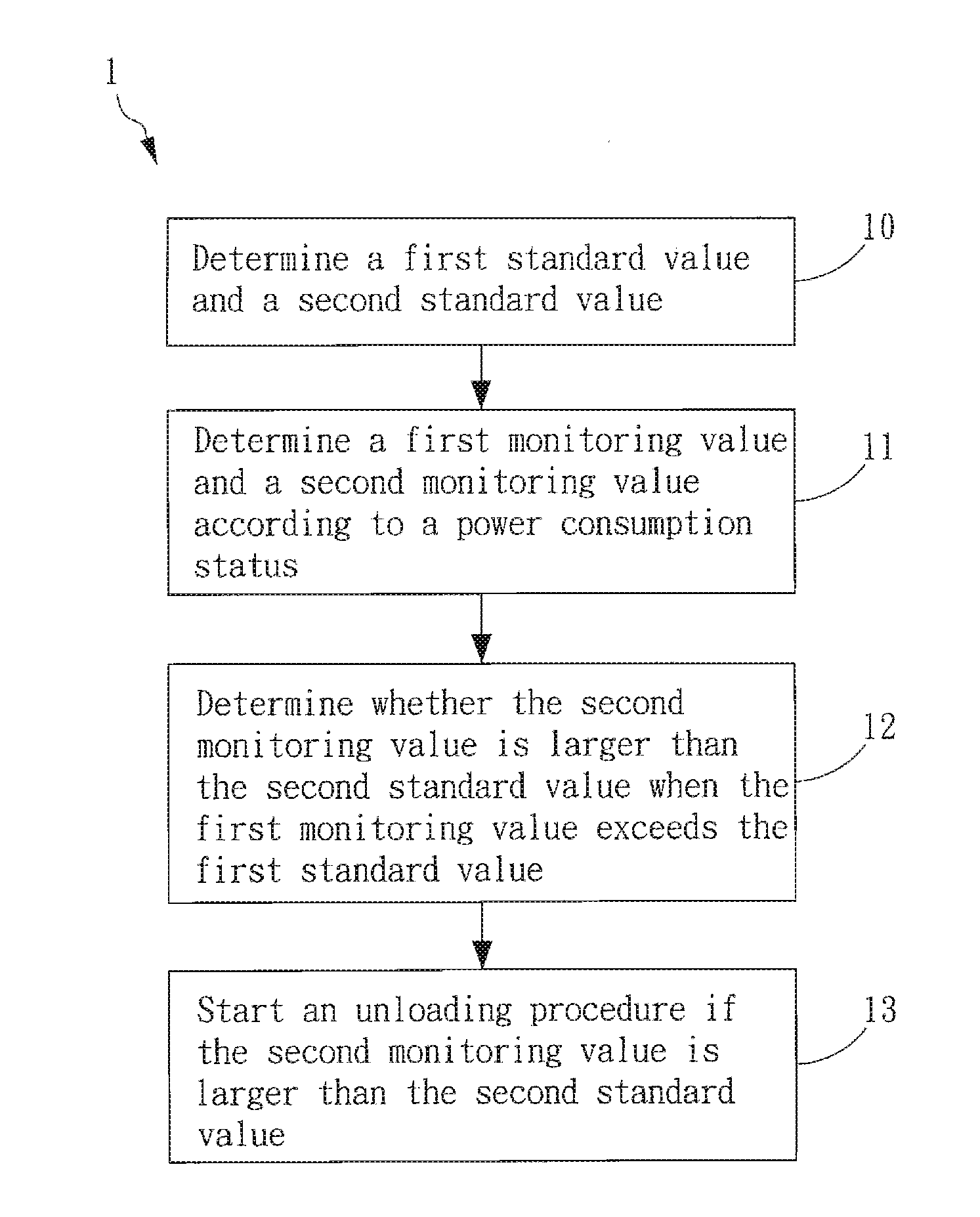
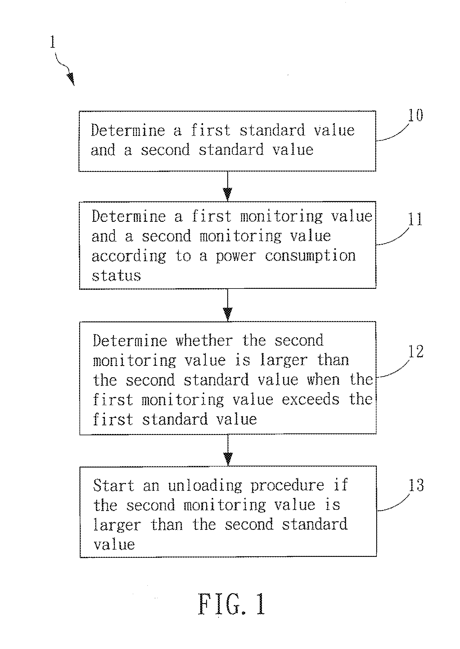
[0022]Please refer to FIG. 1, which is a flowchart of a method for power load management according to the present invention. The method 1 for power load management of the present invention is used in an electrical system such as an air-conditioning system in a building or a large zone. However, the present invention is not limited thereto. In the present invention, the timing for unload / reload is controlled so as to provide reliable electricity and meet the subscribers' requirement with reduced power consumption. In FIG. 2, the method 1 comprises steps as described. First, in Step 10, a first standard value and a second standard value are determined, in the present embodiment, the first standard value and the second standard value represent the consumed power (in kilowatt). The first standard value is smaller than the second standard value. The first standard value is determined by m...


PUM


Abstract

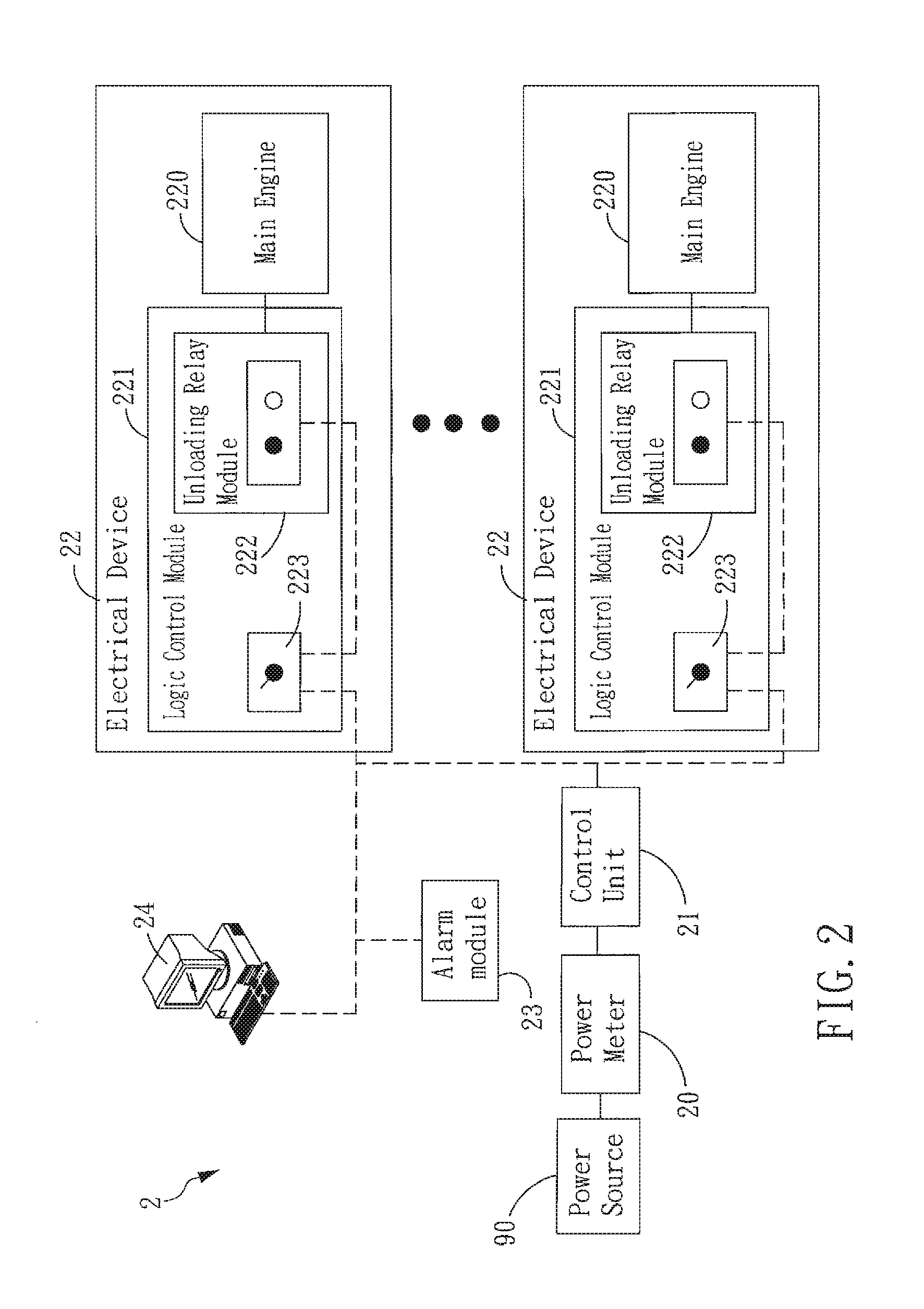
A method for power load management is provided in the present invention, wherein two different standard values are determined to be a basis for regulating power consumption. When power consumption exceeds a first standard value, a monitoring procedure is started to monitor consumption status. If the power consumption exceeds a second standard value, an unloading procedure is processed to reduce the power consumption of electrical devices under operation. In another embodiment, the present invention also provides a system for power load management comprising a control unit coupled to at least one electrical device and a power meter. By means of real-time recording of power consumption in the power meter, the control unit is capable of determining the power consumption status and determining whether it is necessary to unload or reload the at least one electrical device.

Description

BACKGROUND OF THE INVENTION[0001]1. Field of the Invention[0002]The present invention generally relates to a method and a system for power load management and, more particularly, to a method and a system for power load management capable of controlling the timing for unloading or reloading an electrical device according to power consumption thereof.[0003]2. Description of the Prior Art[0004]Due to the raise in oil and coal prices in recent years, the cost of generating power has significantly increased. Moreover, the green house effect worsens the global warming that ecologically affects the earth. Therefore, various measures for energy conservation have been taken throughout the world.[0005]The air conditioner plays an important role in the summer for people living in the subtropical countries. Such an electric device is a power eater even though it brings forth comfort in the room during the summer. Statistically, the power consumption of the air conditioning systems occupies 30˜4...

Claims


Application Information

Patent Timeline
Patent Type & Authority Applications(United States)
IPC IPC(8): G06F1/32G06F1/28
CPCG05B2219/2639H02J3/14H02J2003/146Y04S20/242Y04S20/222Y04S20/224Y02B70/3266Y02B70/3225H02J2310/64H02J2310/14Y02B70/30Y04S50/10Y04S20/00Y02B90/20
Inventor YEH, TUNG-JUNGPENG, SHENG-HSUANKO, HORNG-SHINNHUNG, WEN-TE
Owner IND TECH RES INST
Learn More