Error correction decoding device and reproduction device

a decoding device and error correction technology, applied in the field of decoding technology of error correction codes, can solve the problems of deterioration of throughput, random errors, and signals read from a recording medium such as an optical disk or an hd (hard disk), and achieve high error correction performance, improve throughput, and improve the effect of throughpu

Inactive Publication Date: 2010-08-19
PIONEER CORP
View PDF9 Cites 29 Cited by
  • Summary
  • Abstract
  • Description
  • Claims
  • Application Information

AI Technical Summary

Benefits of technology

[0007]A first objective of the present invention in light of the above is to provide an error correction decoding device and a reproduction device capable of realizing extremely high error correction performan

Problems solved by technology

Signals read from a recording medium such as an optical disk or an HD (hard disk) is not only susceptible to random errors, they are also susceptible to burst errors resulting from the damage of the recording medium or mechanical operation

Method used


Image

  • Error correction decoding device and reproduction device
  • Error correction decoding device and reproduction device
  • Error correction decoding device and reproduction device

Examples


first embodiment

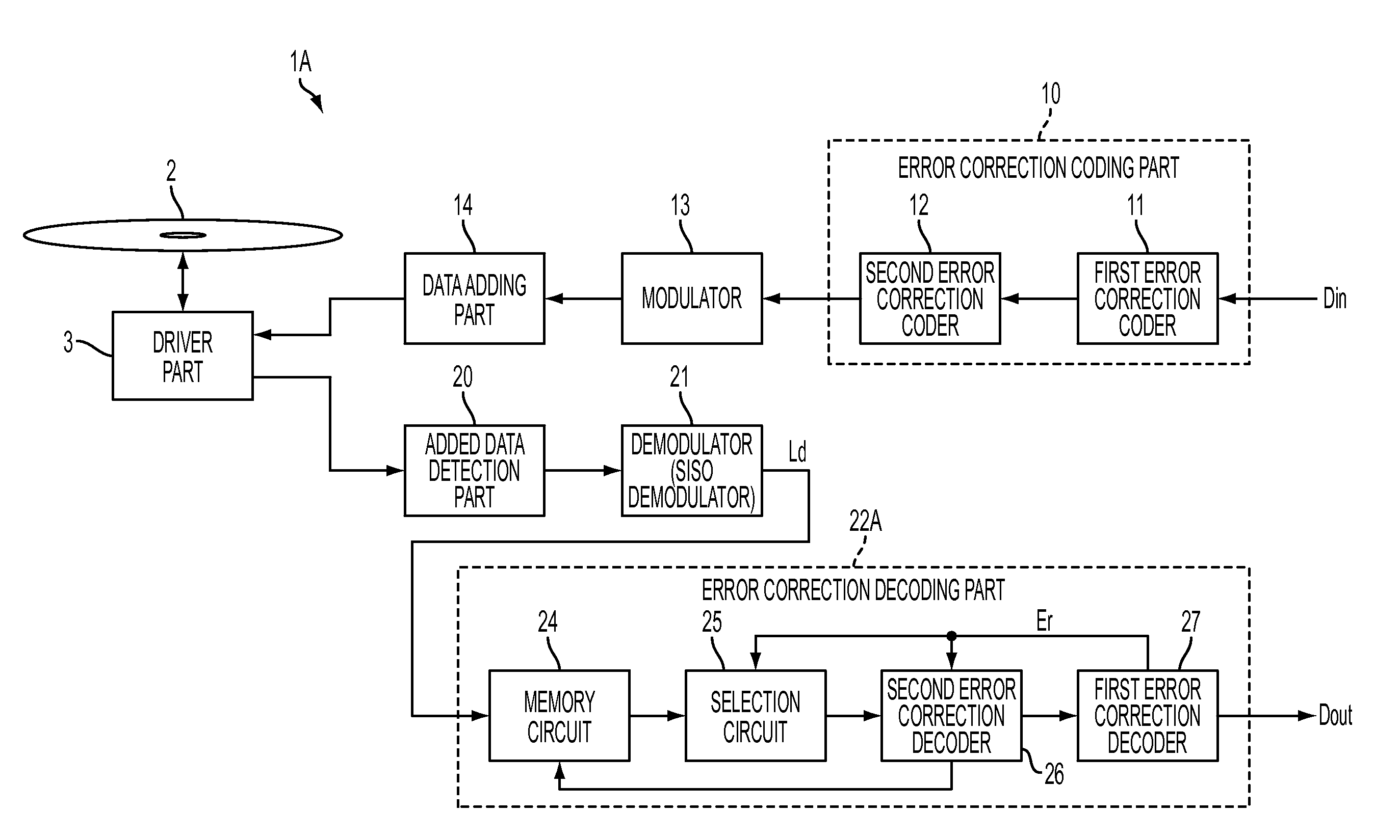
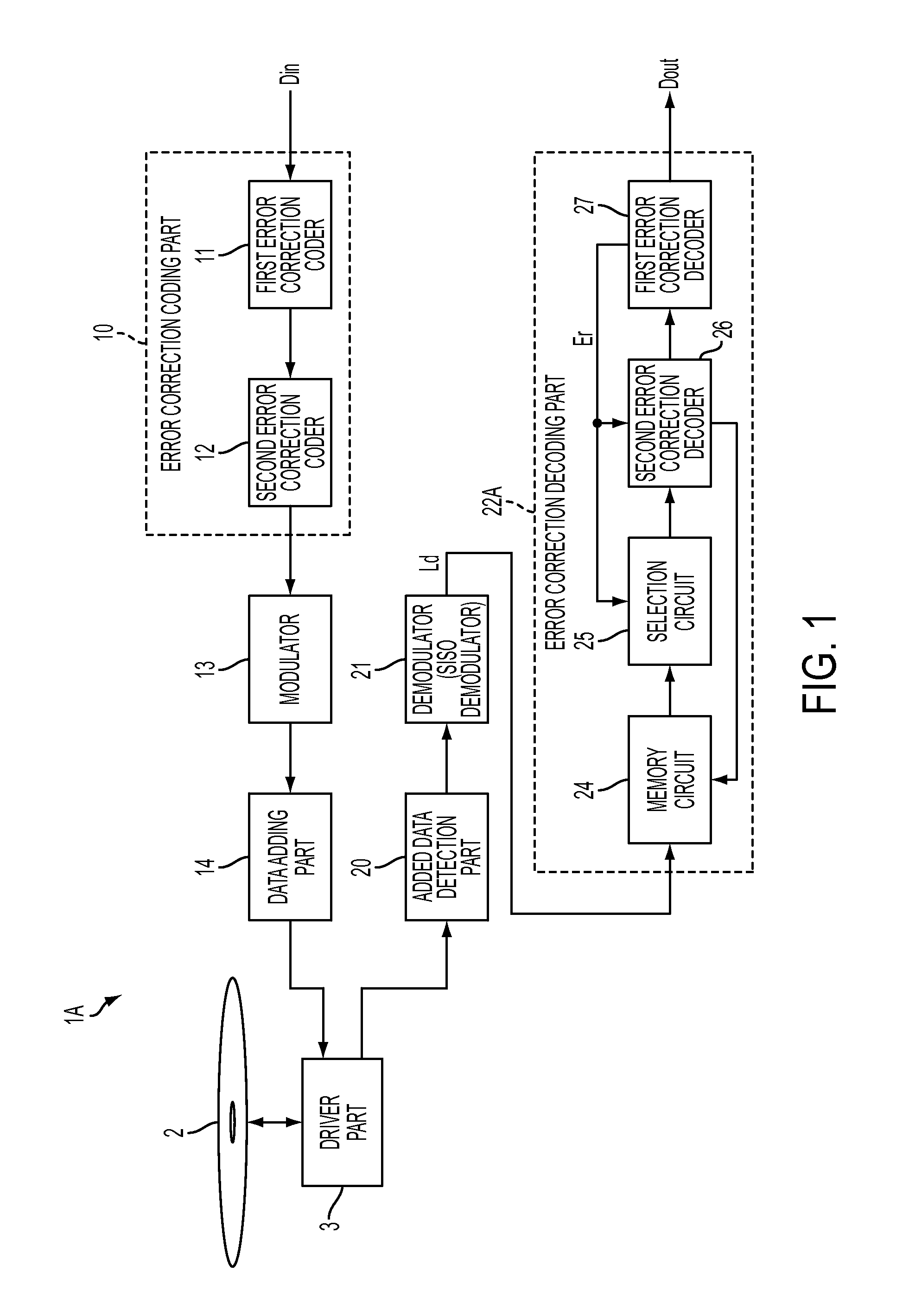
[0056]FIG. 1 is a functional block diagram showing a schematic configuration of a recording / reproduction device 1A as the first embodiment of the present invention. The recording / reproduction device 1A has a function of recording input data (user data) Din in a recording medium 2, and a function of reproducing the recorded data Dout from the recording medium 2. The recording medium 2 may be, for example, optical discs such as a CD (Compact Disc), a DVD (Digital Versatile Disc), a BD (Blu-ray Disc) or an AOD (Advanced Optical Disc), or a holographic memory, a ferroelectric probe memory or an HD (hard disk), and there is no particular limitation. Incidentally, the error correction decoding technology explained below can also be applied to various fields, in addition to the field of recording / reproduction devices, which require error correction decoding.

[0057]The recording / reproduction device 1A includes an error correction coding part 10, a modulator 13, and a data adding part 14. The...

second embodiment

[0104]The second embodiment of the present invention is now explained. FIG. 11 is a functional block diagram showing the schematic configuration of a recording / reproduction device 1B as the second embodiment. The recording / reproduction device 1B is configured the same as the recording / reproduction device 1A (FIG. 1) of the first embodiment excluding the configuration of the error correction decoding part 22B. The error correction decoding part 22B includes a memory circuit 24, a selection circuit 25, a second error correction decoder 26B, and a first error correction decoder 27B. The configuration of the memory circuit 24 and the selection circuit 25 of the error correction decoding part 22B is the same as the configuration of the memory circuit 24 and the selection circuit 25 of the error correction decoding part 22A of the first embodiment.

[0105]FIG. 12 is a diagram showing an example of the configuration of the error correction decoding part 22B of the second embodiment. As shown...

third embodiment

[0118]The third embodiment of the present invention is now explained. FIG. 15 is a functional block diagram showing the schematic configuration of a recording / reproduction device 1C as the third embodiment. The recording / reproduction device 1C is configured the same as the recording / reproduction device 1A (FIG. 1) of the first embodiment excluding the SISO demodulator 21P and the error correction decoding part 22C. Whereas the SISO demodulator 21 of the first embodiment outputs the likelihood information Ld as parallel data, the SISO demodulator 21P of the third embodiment outputs the likelihood information Ld as serial data.

[0119]The error correction decoding part 22C includes an SP converter (serial-parallel converter) 23, a memory circuit 24, a selection circuit 25, a second error correction decoder 26, a first error correction decoder 27C, and a lost position detection part 40. The configuration of the memory circuit 24, the selection circuit 25 and the second error correction d...


PUM


Abstract

A decoding device which performs error correction decoding of encoded data formed from a combination of an outer code for first error correction and an inner code for second error correction is disclosed. The decoding device has: a demodulator for creating a data series of likelihood information values; a second error correction decoder for creating a hard decision value series by executing repetitive decoding for the second error correction based on the likelihood information values; and a first error correction decoder for detecting a lost bit in the hard decision value series and creating an erasure flag indicating the position of the detected lost bit. The second error correction decoder, according to the erasure flag, executes the repetitive decoding based on a likelihood information value not corresponding to the position of the lost bit among the data series of the likelihood information values and a predetermined value that invalidates the likelihood information value corresponding to the position of the lost bit.

Description

TECHNICAL FIELD[0001]The present invention relates to decoding technology of error correction codes, and in particular relates to decoding technology of concatenated codes and iterated codes formed from the combination of an outer code and an inner code.BACKGROUND ART[0002]Error correction technology is essential technology for realizing highly reliable communication systems and information recording systems. Concatenated codes and iterated codes are codes that are formed from a combination of two types of codes (outer code and inner code). For instance, an RS code (Reed-Solomon code) or a BCH code (Bose-Chaudhuri-Hocquenghem code) is broadly used as the outer code, and a convolutional code, a turbo code or an LDPC code (Low Density Parity Check code) is broadly used as the inner code. In particular, the turbo code and the LDPC code are attracting attention as an error correction code for realizing performance that approaches the Shannon limit. The LDPC code and its decoding method ...

Claims


Application Information

Patent Timeline
IPC IPC(8): H03M13/15G06F11/10
CPCH03M13/2957G11B20/1833
Inventor KOBAYASHI, HIDEKI
Owner PIONEER CORP
Why Eureka
Try Eureka