

Automate fluid flow control system
- Summary
- Abstract
- Description
- Claims
- Application Information
AI Technical Summary
Benefits of technology
Problems solved by technology
Method used
Image

Examples
Embodiment Construction
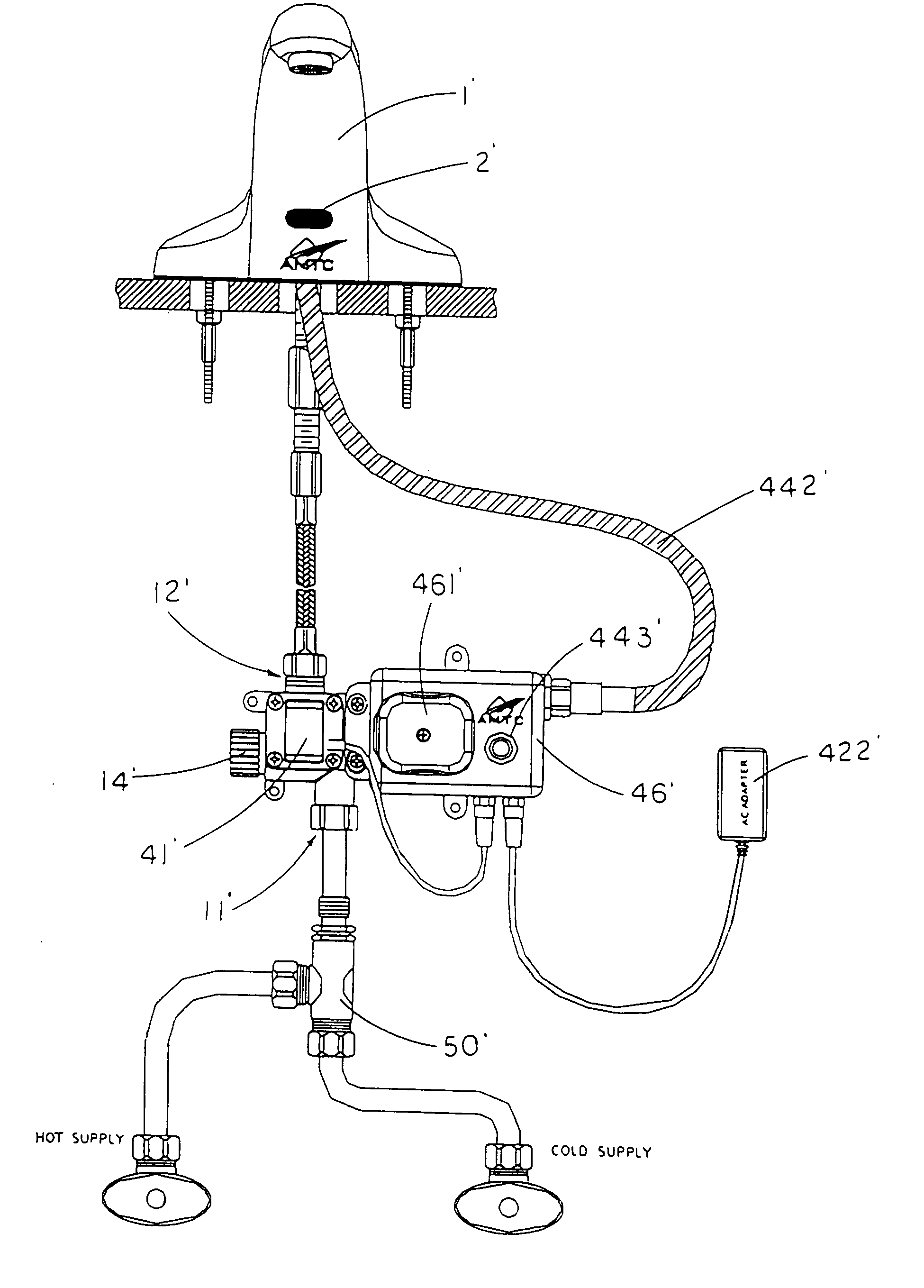
[0044]Referring to FIG. 1 of the drawings, an automate fluid flow control system according to a preferred embodiment of the present invention is illustrated, wherein the automate fluid flow control system is adapted for incorporating with a conventional fluid system, such as a faucet system, a toilet system, a showering system, or even a fluid piping system.
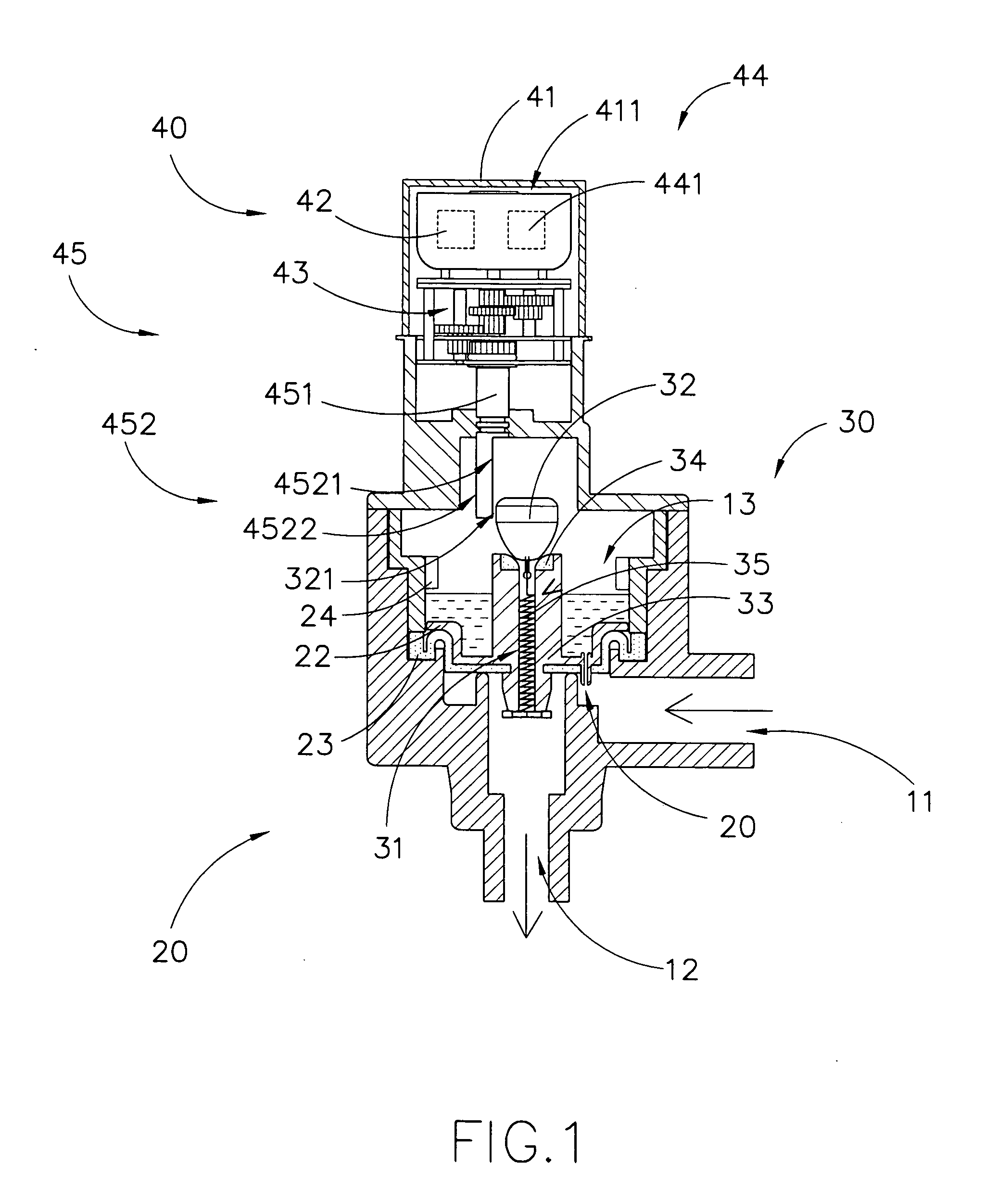
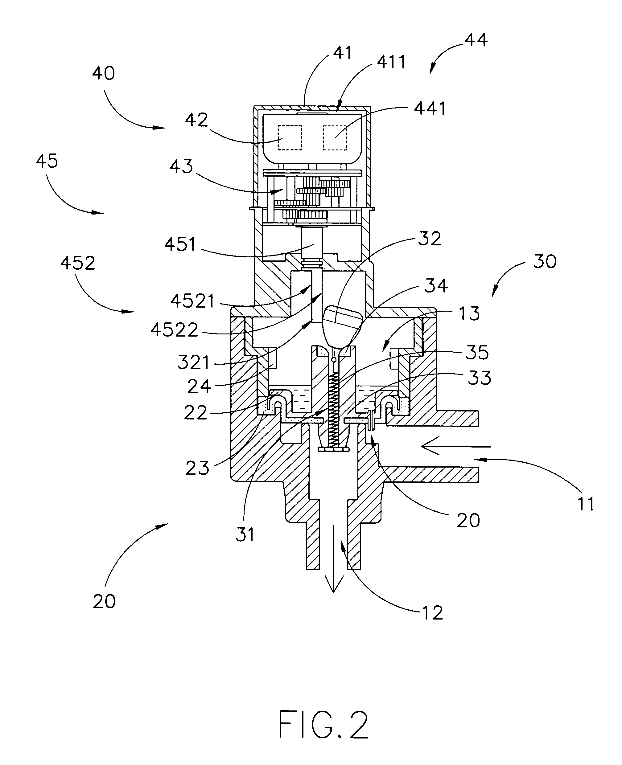
[0045]The fluid system generally has a fluid inlet 11, a fluid outlet 12, and a fluid chamber 13 communicating between the fluid inlet 11 and the fluid outlet 12, wherein a flow of fluid passes from the fluid inlet 11 to the fluid outlet 12 through the fluid chamber 13.
[0046]According to the preferred embodiment, the automate fluid flow control system comprises a valve member 20, a relief valve 30, and a powering assembly 40.
[0047]The valve member 20 is adapted for being sealedly disposed within the fluid chamber 13 to seal a flow of fluid flowing from the fluid inlet 11 to the fluid outlet 12, wherein the valve member 20 is adap...
PUM
 Abstract
Description
Claims
Application Information