Utility Pole Grounding Wire Replacement with an Embedment Method and Device

a technology for grounding wires and poles, applied in the manufacture of wooden sticks, electric cable installations, chemical debarking, etc., can solve the problem of grounding wires that are not visible or accessible on the outside of the poles

Inactive Publication Date: 2010-08-26
QUANTA ASSOC
View PDF21 Cites 14 Cited by
  • Summary
  • Abstract
  • Description
  • Claims
  • Application Information

AI Technical Summary

Problems solved by technology

This results in a grounding wire that is not visible or accessible on the outside of the pole.

Method used


Image

  • Utility Pole Grounding Wire Replacement with an Embedment Method and Device
  • Utility Pole Grounding Wire Replacement with an Embedment Method and Device
  • Utility Pole Grounding Wire Replacement with an Embedment Method and Device

Examples


Embodiment Construction

)

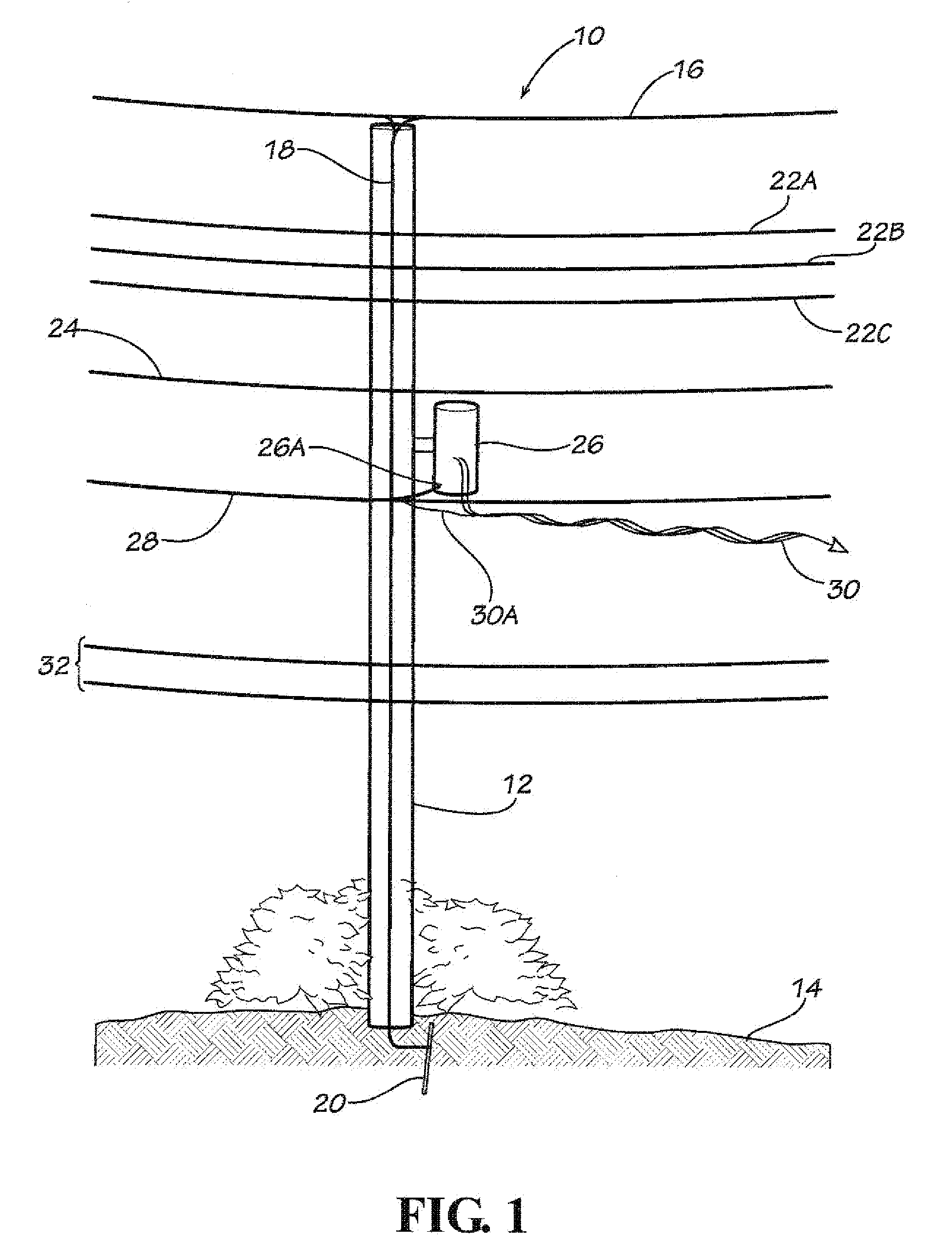
[0015]With reference to FIG. 1, a utility pole 10 is shown. The utility pole 10 for purposes of this application is a wood pole 12 (or other composite allowing mechanical working of the outer surface). The utility pole 10 generally ranges from twenty to one-hundred feet tall with thirty-five feet being a more common pole height. In a normal case the utility poles 10 are buried about six feet deep into the earth's crust 14 and are spaced consecutively, by way of example, about 125 feet apart.

[0016]By way of example, a common utility pole 10 may include all or portions of the following. A static wire 16 extends across the top of the utility pole 10 to bleed lightning surges off the power lines during a storm. A grounding wire (conductor) 18 is connected to the static wire 16 and to a grounding rod 20. The grounding wire 18 runs the entire length of the wood pole 12. Transmission lines 22a, 22b, 22c carry high voltage electricity (69-500 kilovolts) in three phases to substations (not ...


PUM


Abstract

An electric transmission wood pole is selected for installation of a grounding wire using a grounding wire slot cutting device generally having two bases, two elongate guide members, a trolley, and a power tool mounted in the trolley. The two bases are adapted to be strapped to the wood pole. With the grounding wire slot cutting device mounted on the wood pole, a groove is cut along the wood pole. This procedure can be repeated to create a continuous groove along the wood pole. A grounding wire is pushed into the groove, and a sealer is applied over the grounding wire to fill the groove and to seal the grounding wire.

Description

CROSS-REFERENCE TO RELATED APPLICATIONS[0001]This application claims the benefit of U.S. Provisional Application No. 61 / 155,015 filed Feb. 24, 2009.STATEMENTS REGARDING FEDERALLY SPONSORED RESEARCH OR DEVELOPMENT[0002]Not Applicable.NAMES OF THE PARTIES TO A JOINT RESEARCH AGREEMENT[0003]Not Applicable.REFERENCE TO A “SEQUENCE LISTING”, A TABLE, OR A COMPUTER PROGRAM[0004]Not Applicable.BACKGROUND[0005]Copper theft poses a threat to customer safety in the utility industry. Power companies use copper wire to ground high-voltage apparatus that sit atop wooden utility or power poles. This copper wire is traditionally stapled to a wood pole from the top of the pole to just below the ground line, where it is attached to a ground rod buried perhaps eight feet into the earth. These ground wires provide system protection from lightning strikes, supply an alternate path for the neutral conductor in alternating current systems, and ground the metal cases of transformers and related equipment....

Claims


Application Information

Patent Timeline
Patent Type & Authority Applications(United States)
IPC IPC(8): B27M3/00
CPCH02G7/205H02G1/02
Inventor HANNAY, RICHARD CHARLES
Owner QUANTA ASSOC
Why Eureka
Try Eureka