Arrangement for installing electric cables in the floor region of an aircraft
- Summary
- Abstract
- Description
- Claims
- Application Information
AI Technical Summary
Benefits of technology
Problems solved by technology
Method used
Image
Examples
Embodiment Construction
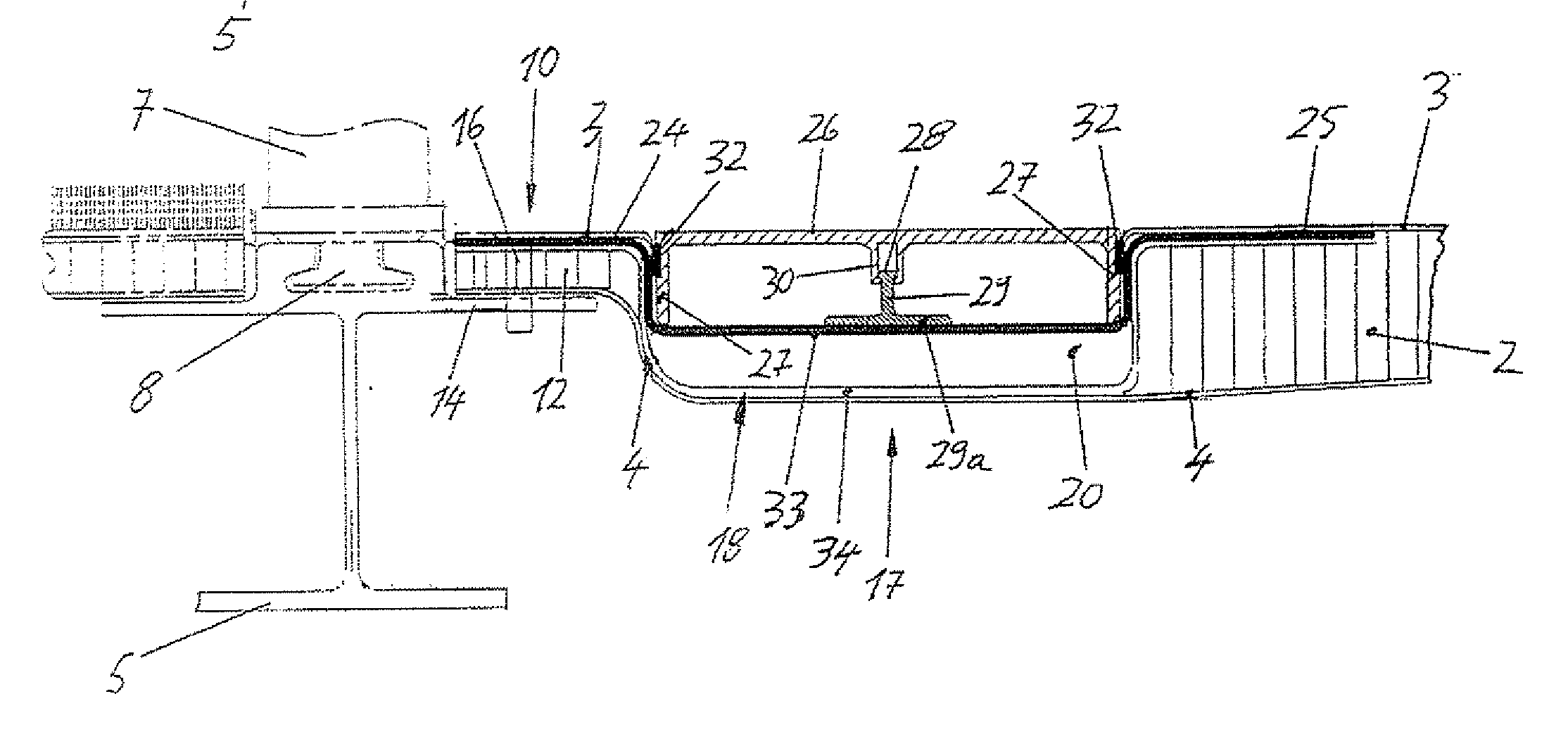
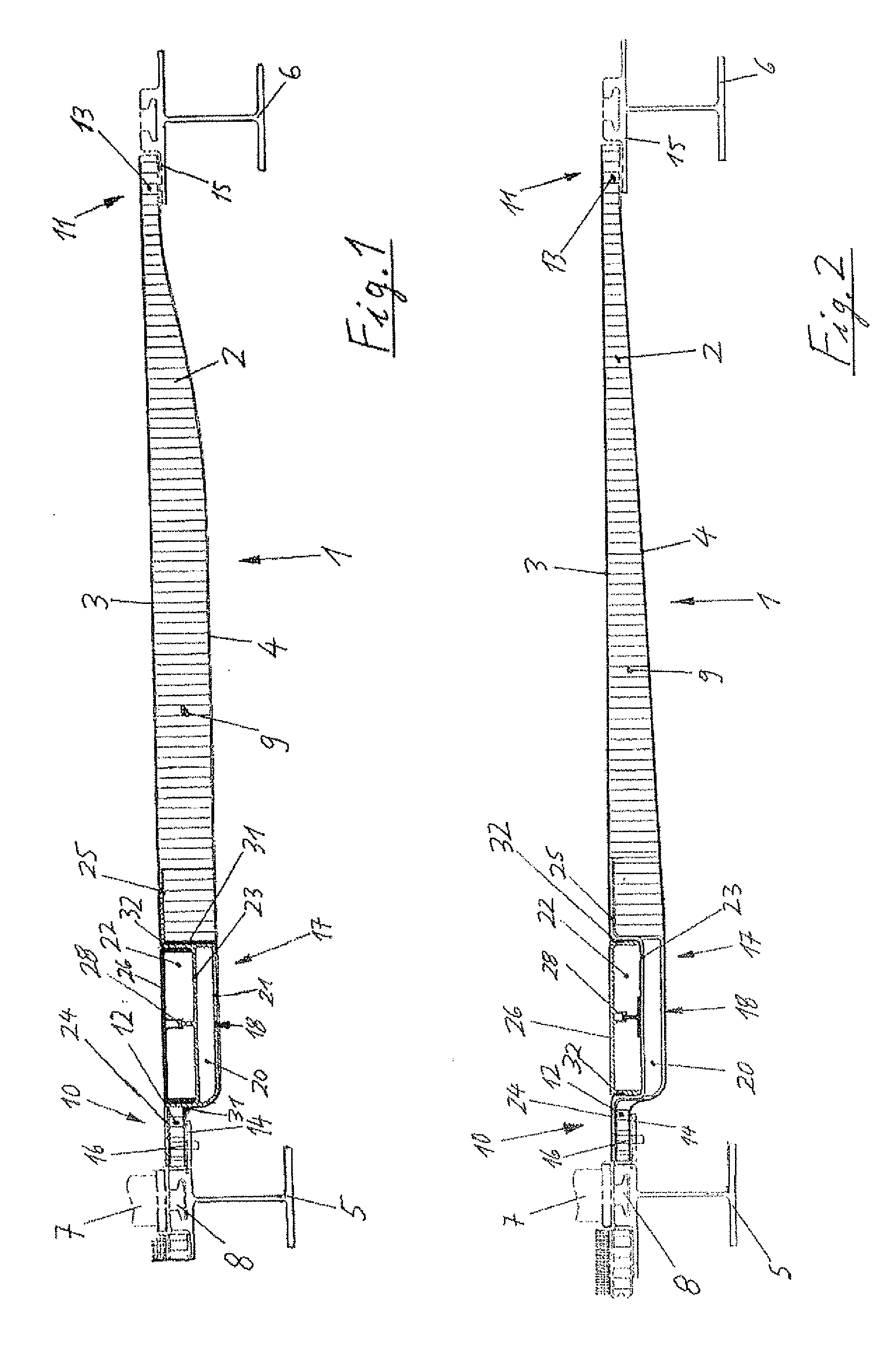
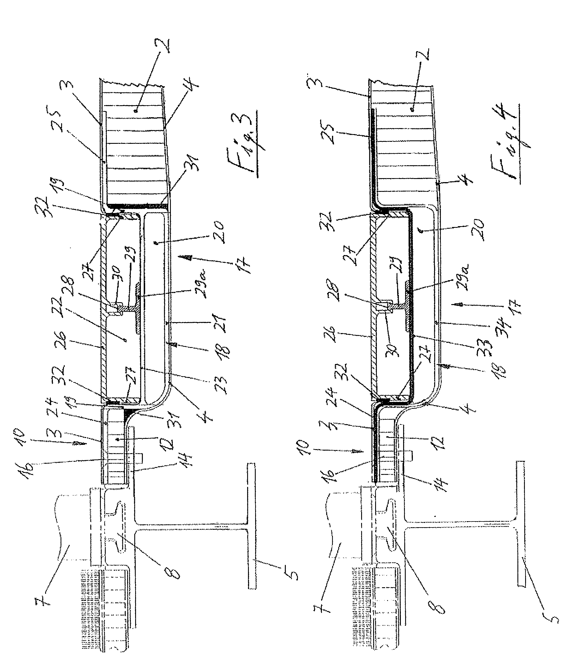
[0016]In FIG. 1, a floor plate 1 is realized in the form of a sandwich component that consists of a honeycomb structure 2 with two outer cover layers 3 and 4, wherein the honeycomb structure 2 may consist of plastic and the cover layers 3 and 4 may consist of plastic that is reinforced with carbon fibers or glass fibers. For example, these outer cover layers may consist of a carbon fibre reinforced plastic (CFK)-layer that is situated adjacent to the honeycomb structure, a central CFK-layer and an outer glass fibre reinforced plastic (GFK)-layer that are not graphically illustrated. The floor plate 1 is arranged between the seat rails 5 and 6 that extend parallel to one another in the longitudinal direction of the aircraft and serve for attaching seat legs 7 of one or more passenger seat(s) by means of conventional tongue and groove clamping connections 8. It may have a width, for example, of 493 mm between the seat rails 5 and 6 while its length may extend over one seat or several ...
PUM
| Property | Measurement | Unit |
|---|---|---|
| Length | aaaaa | aaaaa |
| Force | aaaaa | aaaaa |
| Electrical conductor | aaaaa | aaaaa |
Abstract
Description
Claims
Application Information
 - R&D
- Intellectual Property
- Life Sciences
- Materials
- Tech Scout
- Unparalleled Data Quality
- Higher Quality Content
- 60% Fewer Hallucinations
Browse by: Latest US Patents, China's latest patents, Technical Efficacy Thesaurus, Application Domain, Technology Topic, Popular Technical Reports.
© 2025 PatSnap. All rights reserved.Legal|Privacy policy|Modern Slavery Act Transparency Statement|Sitemap|About US| Contact US: help@patsnap.com


