Input apparatus, input display apparatus, and electronic device

a display device and input technology, applied in the field of input display devices, can solve the problems of difficult to realize a thinner apparatus and increase the thickness of the input display device, and achieve the effect of thin configuration and thin configuration

Inactive Publication Date: 2010-08-26
SEIKO EPSON CORP
View PDF5 Cites 72 Cited by
  • Summary
  • Abstract
  • Description
  • Claims
  • Application Information

AI Technical Summary

Benefits of technology

[0008]In the input apparatus according to the first aspect of the invention, the light-transmissible substrate capable of allowing light to pass therethrough is provided at the border between the input unit and the illumination unit so that the light-transmissible substrate is shared between the input unit and illumination unit, as described above; therefore, for example, the input unit is configured on one side of the light-transmissible substrate and the illumination unit is configured on the other side of the light-transmissible substrate, thus making it possible to realize a configuration in which the input unit and the illumination unit are integrated. Accordingly, the total thickness of the input unit and the illumination unit decreases, as opposed to a case in which an input unit and an illumination unit configured separately are simply layered; this makes it possible to suppress an increase in the total thickness of the input unit and the illumination unit. It is therefore possible to realize a thinner configuration for the apparatus.
[0009]It is preferable, in the input apparatus according to the aforementioned first aspect of the invention, for the illumination unit to include: a first electrode layer formed upon the light-transmissible substrate, which is shared with the input unit, on the side opposite to the side of the input unit; a light-emitting layer formed so as to cover the first electrode layer; and a light-emitting element portion configured of a second electrode layer formed so as to cover the light-emitting layer; and for the light-emitting element portion to irradiate light as a result of a predetermined voltage being applied to the first electrode layer and the second electrode layer. According to this configuration, an integrated configuration can easily be realized using the light transmissible substrate that is shared between the input unit and the illumination unit that includes the light-emitting element portion.
[0013]According to this configuration, with the input display apparatus according to the aforementioned second aspect of the invention, it is possible to realize an integrated configuration of the input unit and the illumination unit in the input apparatus. Accordingly, the total thickness of the input unit and the illumination unit decreases, which makes it possible to suppress an increase in the total thickness of the input unit and the illumination unit. Furthermore, by sharing the light-transmissible substrate between the input unit and the illumination unit of the input apparatus, the number of border surfaces between input unit and illumination unit can be reduced, which makes it possible to execute a reflective display using the display unit while suppressing light irradiated from the illumination unit from reflecting or refracting at the border surfaces between the input unit and illumination unit.
[0015]An electronic device according to a third aspect of the invention includes an input apparatus having one of the configurations described above. According to such a configuration, it is possible to achieve an electronic device that includes an input apparatus capable of realizing a thinner configuration.
[0016]An electronic device according to a fourth aspect of the invention includes an input display apparatus having one of the configurations described above. According to such a configuration, it is possible to achieve an electronic device that includes an input display apparatus capable of realizing a thinner configuration.

Problems solved by technology

However, with the input display apparatus disclosed in the aforementioned JP-A-11-344695, the touch panel and illumination unit are provided separately, resulting in an issue in that the thickness of the input display apparatus increases by that amount.
Accordingly, there is a problem in that it is difficult to realize a thinner apparatus.

Method used


Image

  • Input apparatus, input display apparatus, and electronic device
  • Input apparatus, input display apparatus, and electronic device
  • Input apparatus, input display apparatus, and electronic device

Examples


first embodiment

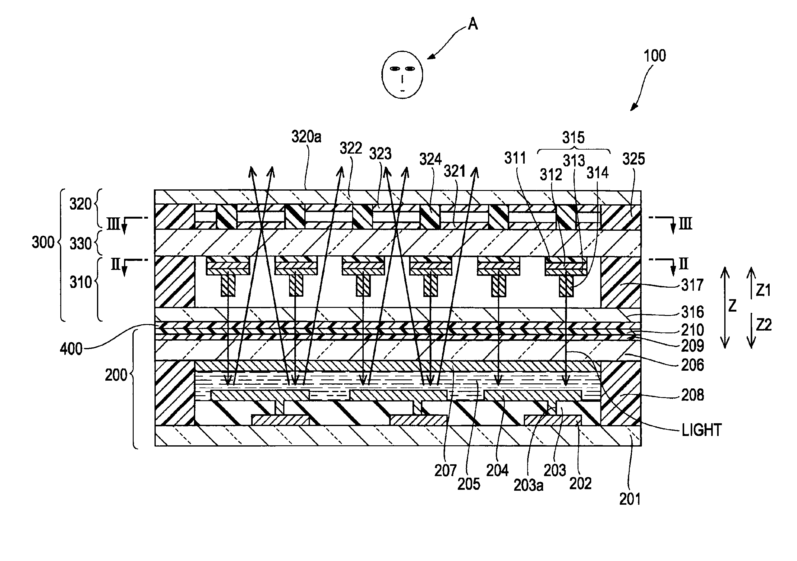
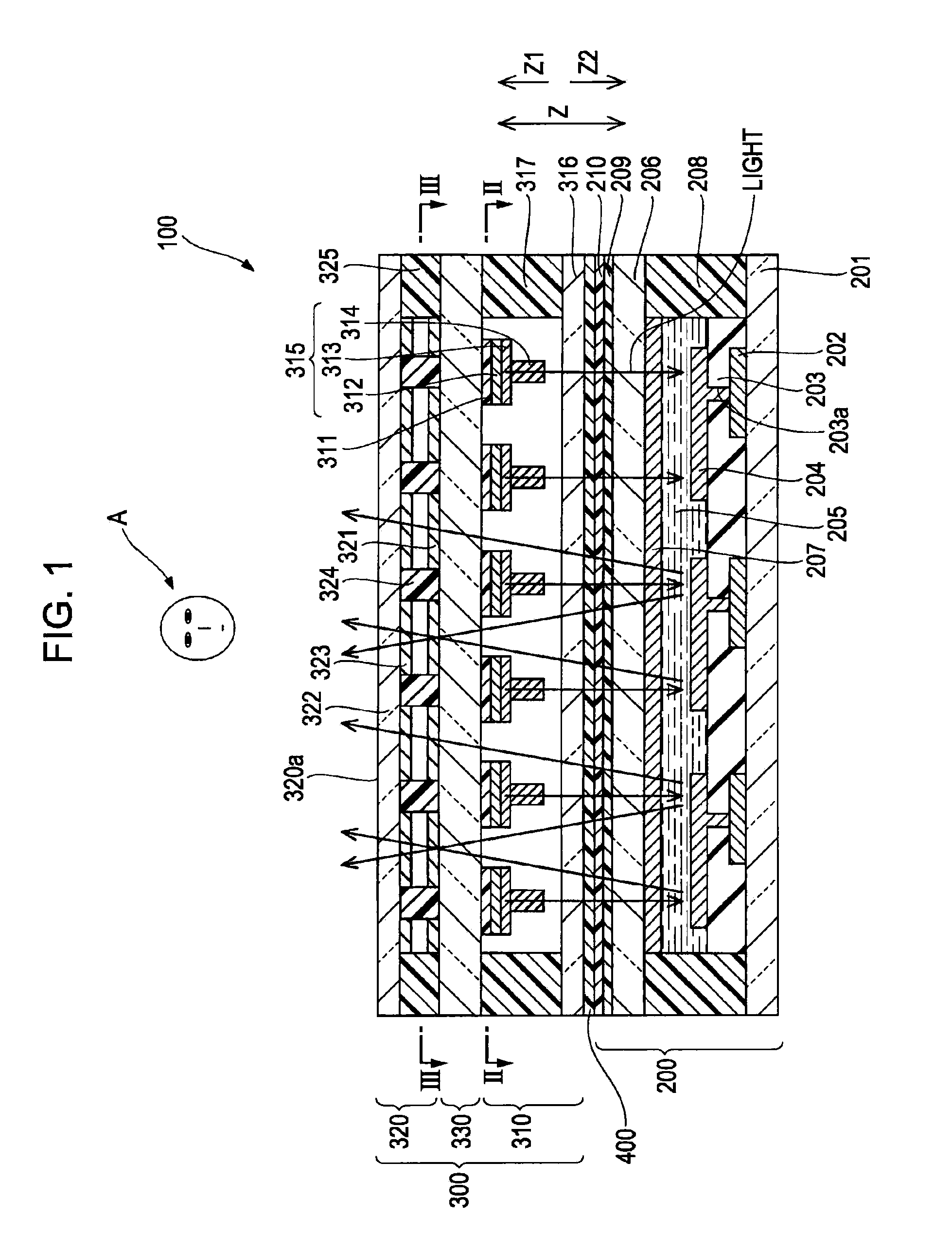
[0028]Hereinafter, the configuration of an input display apparatus (display apparatus) 100 according to a first embodiment of the invention will be described with reference to FIGS. 1 through 3.

[0029]As shown in FIG. 1, the input display apparatus 100 according to the first embodiment includes a reflective liquid-crystal display unit 200 and a front-lit integrated touch panel 300. Note that the reflective liquid-crystal display unit 200 is an example of a “liquid-crystal display unit” according to the invention, and the front-lit integrated touch panel 300 is an example of an “input apparatus” according to the invention. The reflective liquid-crystal display unit 200 and the front-lit integrated touch panel 300 are bonded together by a bonding layer 400, which is configured of a light-curable or heat-curable resin.

[0030]The reflective liquid-crystal display unit 200 includes a TFT substrate 201 configured of a light-transmissible material such as glass or the like. Multiple TFTs (Th...

second embodiment

[0045]Next, a second embodiment will be described with reference to FIGS. 4 and 5. As opposed to the aforementioned first embodiment, which includes a resistive touch panel 320, the second embodiment describes an input display apparatus 101 that includes an electrostatic capacitance touch panel 340. Note that the electrostatic capacitance touch panel 340 is an example of an “input unit” according to an aspect of the invention.

[0046]As shown in FIG. 4, in the electrostatic capacitance touch panel 340 of a front-lit integrated touch panel 300a in the input display apparatus 101 according to the second embodiment, light-transmissible electrode portions 341 configured of a transparent conductive material such as ITO are formed in regions corresponding to a coordinate input surface 340a (see FIG. 5) upon the light-transmissible substrate 330. Note that the front-lit integrated touch panel 300a is an example of an “input apparatus” according to an aspect of the invention, and the light-tr...


PUM


Abstract

An input apparatus includes a single light-transmissible substrate, an input unit including a coordinate input surface formed upon one surface of the light-transmissible substrate, and an illumination unit formed upon the other surface of the light-transmissible substrate.

Description

BACKGROUND[0001]1. Technical Field[0002]The present invention relates to an input apparatus, an input display apparatus, and an electronic device, and particularly relates to an input apparatus, an input display apparatus, and an electronic device provided with an input unit and an illumination unit.[0003]2. Related Art[0004]An input display apparatus provided with an input unit and an illumination unit has been previously known (for example, see JP-A-11-344695). The input display apparatus disclosed in the aforementioned JP-A-11-344695 includes a touch panel through which a viewer can make inputs (that is, an input unit), an illumination unit, provided separately from the input unit, that has a light source configured of an LED or the like provided on the side of the touch panel opposite to the viewer side and a light guide plate for guiding the light from the light source, and a reflective liquid-crystal display provided on the side of the light source opposite to the viewer side ...

Claims


Application Information

Patent Timeline
Patent Type & Authority Applications(United States)
IPC IPC(8): G06F3/041
CPCG02F1/13338G02F2001/133616G06F3/045G06F3/044G06F3/0412G06F3/0445G06F3/0447G02F1/133616
Inventor HIROTA, TAKENORI
Owner SEIKO EPSON CORP
Why Eureka
Try Eureka