Communication system and relay apparatus

a relay and communication system technology, applied in the field of communication systems, can solve the problems of plurality of relays, difficult to reduce increase etc., and achieve the effect of reducing the communication load of a communication line and increasing the delay of data transmission

Inactive Publication Date: 2010-08-26
AUTONETWORKS TECH LTD +2
View PDF12 Cites 61 Cited by
  • Summary
  • Abstract
  • Description
  • Claims
  • Application Information

AI Technical Summary

Benefits of technology

[0010]However, it is difficult to reduce communication load of a communication line with a configuration that a gateway apparatus relays data

Problems solved by technology

However, it is difficult to reduce communication load of a communication line with a configuration that a gateway apparatus relays data sen

Method used


Image

  • Communication system and relay apparatus
  • Communication system and relay apparatus
  • Communication system and relay apparatus

Examples


embodiment 1

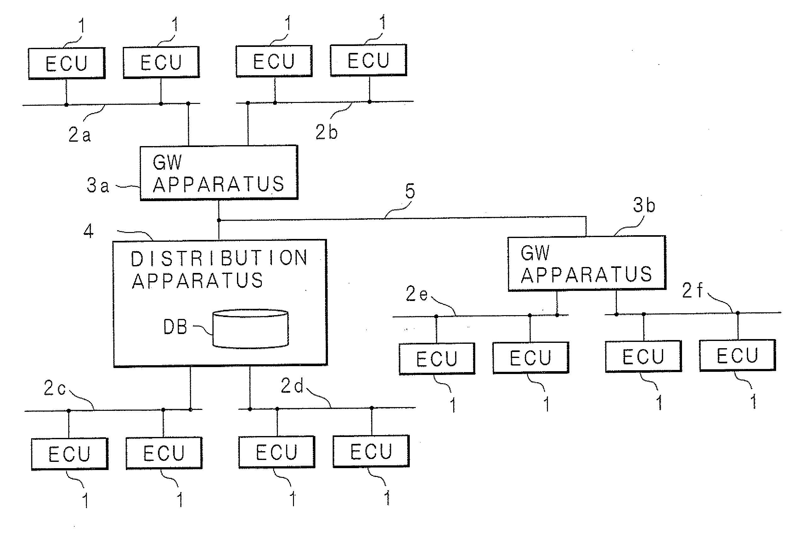
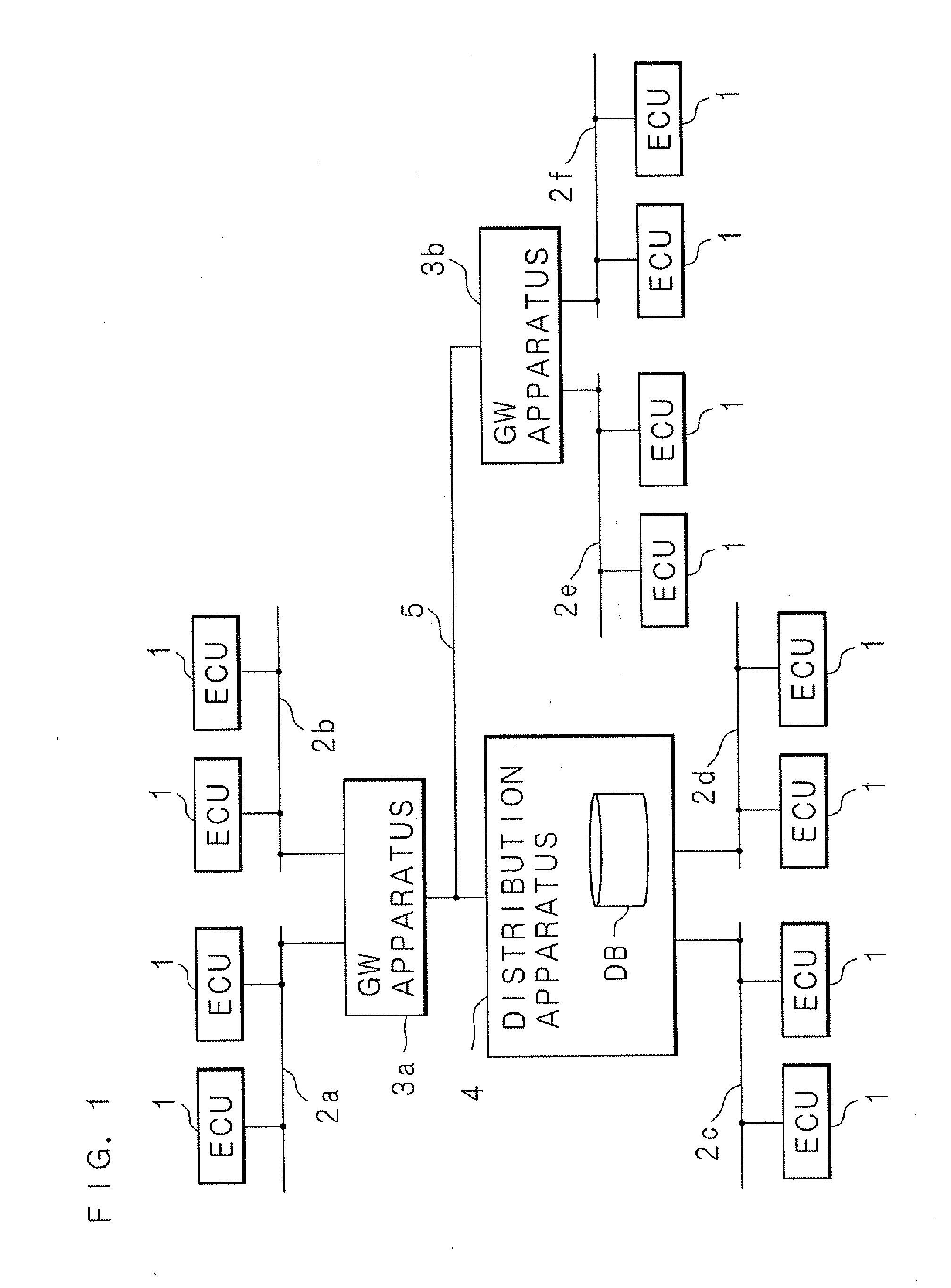
[0078]FIG. 1 is a block diagram showing components of a communication system mounted on a motor vehicle according to an embodiment 1. The Communication System Mounted on the Motor vehicle according to the embodiment 1 includes: communication apparatuses that are ECUs 1, 1, . . . , and transmit and receive data; communication lines 2a, 2b, 2c, 2d, 2e, 2f that connect ECUs 1, 1, . . . ; GW apparatuses 3a, 3b that relay data transmitted among ECUs 1, 1, . . . respectively connected to different communication lines 2a, 2b, 2c, 2d, 2e, 2f; a distribution apparatus 4 that is a specific GW apparatus; and a communication line 5 that connects the GW apparatuses 3a, 3b and the distribution apparatus 4.

[0079]The ECUs 1, 1, . . . can send data including numerical information of several physical quantities, such as measured values, computed values and control values. Furthermore, the ECUs 1, 1, . . . can control an engine, brake or the like, with utilizing a microcomputer. For example, an ECU 1 ...

embodiment 2

Alternate Embodiment 2

[0148]Next, it will be described as an alternate embodiment 2 about the case that an ECU 1, 1, . . . is connected to a plurality of branch lines among the branch lines 2a, 2b, 2c, 2d, 2e, 2f, i.e., about multiple connections. The following description is illustrated about a procedure that the control unit 40 of the distribution apparatus 4 updates the connection information when an ECU 1 provided with a number “1” is connected to both the branch line 2b and the branch line 2f as the multiple connections.

[0149]The configurations of the communication system mounted on the motor vehicle of the alternate embodiment 2 is similar to those of the embodiment 2, except for configurations that one ECU 1 is connected to both the branch line 2b and the branch line 2f and that the control unit 40 of the distribution apparatus 4 stores connection information based on such the multiple connections. The same numerals are utilized for configurations of the alternate embodiment ...

embodiment 3

[0162]In the Embodiments 1 and 2, it is Configured that the distribution apparatus 4 is the specific GW apparatus including the storage region utilized for the database DB, which is different from the other GW apparatuses 3a, 3b. However, it is considered about the case that, for example, the GW apparatus 3a should work as “the distribution apparatus (a specific relay apparatus)” in accordance with the connection configuration on the trunk line 5 and the message transmission path, rather than the distribution apparatus 4 works as “the distribution apparatus”. In view of such a case, it is configured in an embodiment 3 that any GW apparatuses connected to the trunk line 5 include such storage regions utilized for the database and can work as the distribution apparatus. Furthermore, it is configured in the embodiment 3 that one GW apparatus is automatically selected from the GW apparatuses and works as the distribution apparatus that is the specific GW (relay) apparatus.

[0163]FIG. 16 ...


PUM


Abstract

A trunk line topology network is configured with: ECUs 1, 1, . . . being communication apparatuses transmitting and receiving data; and GW apparatuses 3a, 3b and a distribution apparatus 4 being a specific GW apparatus 4 that are connected to a communication line 5 being a trunk line, for relaying, through the GW apparatuses, data transmitted among the ECUs 1, 1, . . . . The distribution apparatus 4 includes a storage region utilized for a database DB. The data transmitted from the ECUs 1, 1, . . . are relayed by the GW apparatuses 3a, 3b and then aggregated by the distribution apparatus 4. The relayed data are stored once on the database DB. When transmitting data to the ECUs 1, 1, . . . , the distribution apparatus 4 reads out data from the database DB and transmits the data at the adjusted transmission timing. The GW apparatuses 3a, 3b relay the transmitted data.

Description

[0001]This application is the national phase under 35 U.S.C. §371 of PCT International Application No. PCT / JP 2008 / 068178 which has an International filing date of Oct. 6, 2008 and designated the United States of America.BACKGROUND OF THE INVENTION[0002]1. Field of the Invention[0003]The present invention relates to a communication system that performs data transmission among communication apparatuses via a relay apparatus. Especially, the present invention relates to a communication system and a relay apparatus included in the communication system for preventing data transmission delay and for reducing a communication load.[0004]2. Description of Related Art[0005]It is recently known in several fields to utilize a system having many communication apparatuses, in which each communication apparatus is provided with a certain function and connected with other communication apparatuses in order to perform many operations through data exchange between many communication apparatuses. For...

Claims


Application Information

Patent Timeline
IPC IPC(8): H04L12/56B60R16/023H04L12/28H04L12/46
CPCH04L12/40H04L2012/40273H04L2012/40215H04L12/4625
Inventor HISADA, TOSHIYA
Owner AUTONETWORKS TECH LTD
Why Eureka
Try Eureka