
Methods And Systems For Laser Treatment Using Non-Uniform Output Beam

a laser treatment and output beam technology, applied in the field of laser treatment using non-uniform output beam, can solve the problems of skin may take a month or more to heal under such a procedure, low efficiency of methodology, pain and epidermal damage, etc., and achieves the effect of reducing peak energies, reducing the area of patients, and high-absorption of laser radiation

Active Publication Date: 2010-08-26
CYNOSURE
View PDF28 Cites 25 Cited by
  • Summary
  • Abstract
  • Description
  • Claims
  • Application Information

AI Technical Summary

Benefits of technology

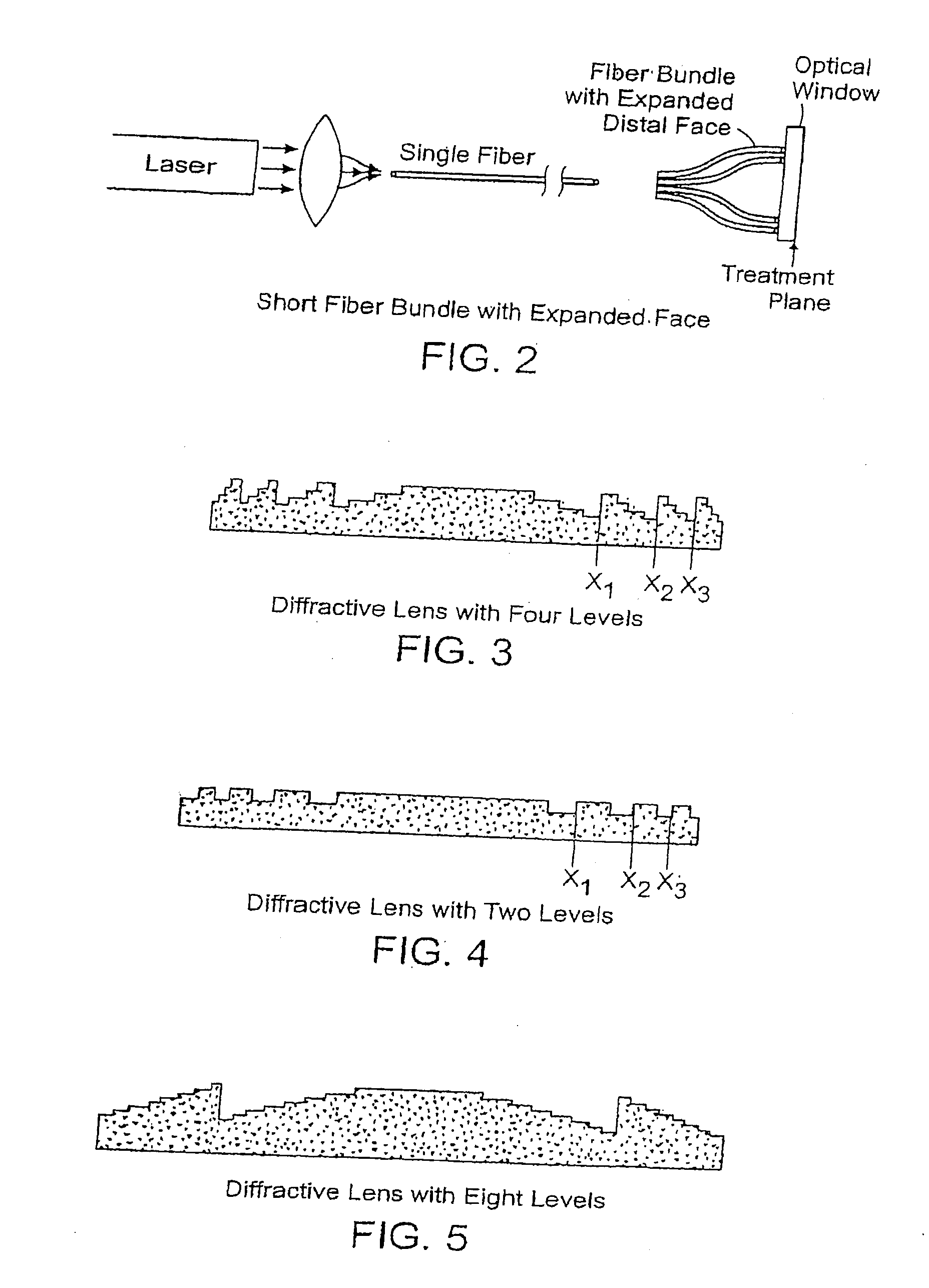
"The present invention relates to methods and apparatus for skin rejuvenation treatment using non-uniform laser radiation. The invention provides a treatment beam with high-intensity zones that heat select portions of the target tissue for collagen destruction and shrinkage, while the surrounding tissue is stimulated for collagen production. The treatment beam can be generated using a solid-state laser source, such as an Nd:YAG laser, and can have a non-uniform energy profile with high-intensity zones and low-intensity zones. The optical system can comprise a fiber bundle or a diffractive lens array. The invention allows for simultaneous treatment of a large area of tissue, minimizing damage to the skin. The average fluence of the treatment beam is less than about 10 J / cm2."

Problems solved by technology

While carbon dioxide lasers may remove about 150 microns of skin, that skin may take a month or more to heal under such a procedure.
However they lack the coagulation characteristics and thus allow more bleeding than a carbon dioxide laser during use.
This methodology however, has a low efficiency, and an aggressive cooling method must be used on to the skin so as to minimize damaging the top or upper layer thereof and also to minimize pain generation.
This level of energy often causes pain and epidermal damage.
However, the parameters of the treatment beam in this method are not optimal for skin rejuvenation treatment.

Method used


Image

  • Methods And Systems For Laser Treatment Using Non-Uniform Output Beam
  • Methods And Systems For Laser Treatment Using Non-Uniform Output Beam
  • Methods And Systems For Laser Treatment Using Non-Uniform Output Beam

Examples


Embodiment Construction

[0033]A description of preferred embodiments of the invention follows.

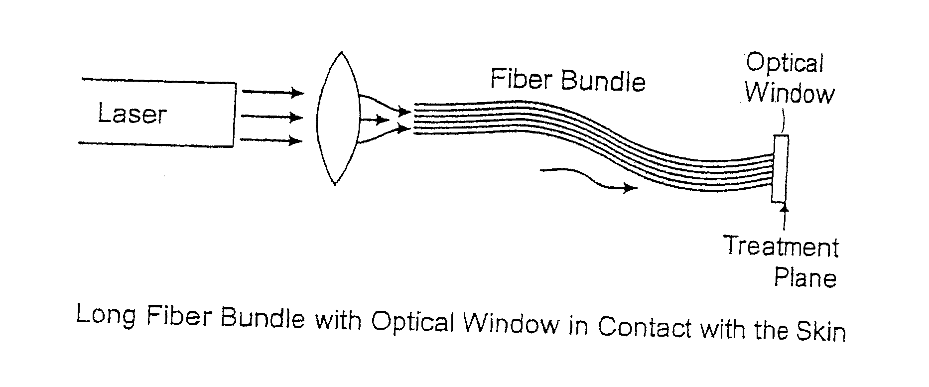
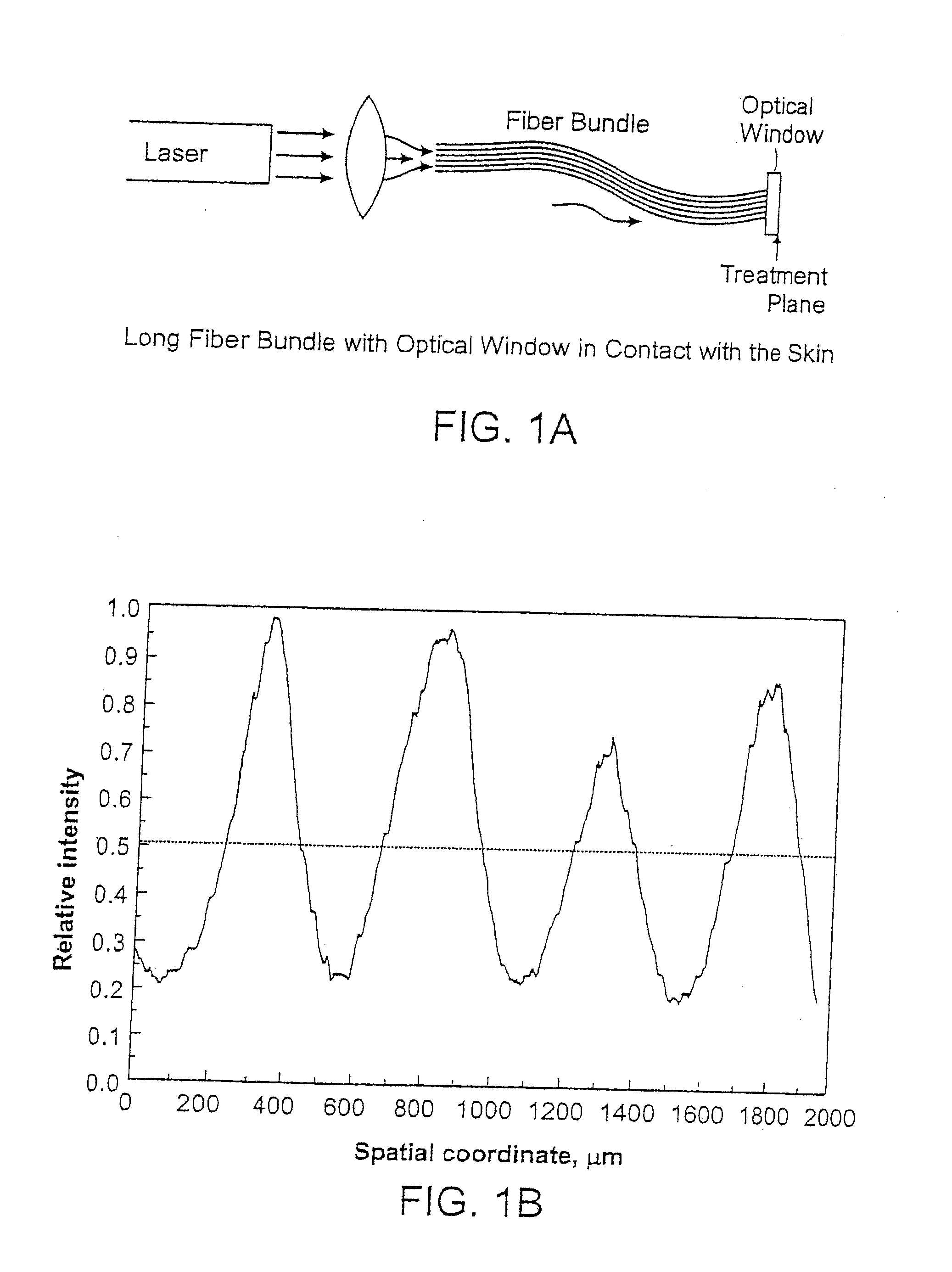
[0034]As shown in FIG. 1A, the apparatus includes a laser source that emits an output beam. The beam is coupled into a bundle of optical fibers using one or more focusing lenses. The bundle preferably contains between 1000 and 2000 separate fibers. Typically, each fiber has a diameter of about 100-200 microns. The output laser beam is thus directed to 1000-2000 smaller beams, each of which traverses the length of the fiber bundle in individual optical fibers. The fiber bundle terminates at its distal end at an optical window that can be held in direct contact with the patient's skin. The window is approximately 1-5 mm thick, and protects the output face of the fiber bundle from contamination, and also permits the beam emitted from each fiber to diverge before it reaches the patient's skin, preferably so that each beam partially overlaps with the beam(s) from adjacent fibers in the bundle.

[0035]The fibers in the bu...


PUM


Abstract

Disclosed herein are methods and systems for treatment, such as skin rejuvenation treatment, use non-uniform laser radiation. A high-intensity portion of the laser radiation causes collagen destruction and shrinkage within select portions of the treatment area, while a lower-intensity portion of the radiation causes fibroblast stimulation leading to collagen production across other portions of the treatment area. An output beam from a laser source, such as an Nd:YAG laser, is coupled into an optical system that modifies the beam to provide a large-diameter beam having a nonuniform energy profile, comprised of a plurality of high-intensity zones surrounded by lower-intensity zones within the treatment beam. The higher-intensity zones heat select portions of the target tissue to temperatures sufficient for a first treatment (e.g. collagen shrinkage), while the lower-intensity zones provide sufficient energy for a second treatment (e.g. stimulated collagen production).

Description

RELATED APPLICATION[0001]This application is a continuation of U.S. patent application Ser. No. 11 / 347,672, filed on Feb. 3, 2006, entitled “Methods and Systems for Laser Treatment Using Non-Uniform Output Beam”, which claims the benefit of U.S. provisional application No. 60 / 673,914, filed on Apr. 22, 2005, the entire teachings of which are incorporated herein by reference.BACKGROUND OF THE INVENTION[0002]Plastic surgeons, dermatologists and their patients continually search for new and improved methods for treating the effects of an aging skin. One common procedure for rejuvenating the appearance of aged or photodamaged skin is laser skin resurfacing using a carbon dioxide laser. The carbon dioxide laser energy is absorbed by tissue water causing vaporization of the outer skin layer. Carbon dioxide lasers have been utilized for approximately three decades. However it has only been the past few years that these lasers have been arranged to remove only thin tissue layers with minima...

Claims


Application Information

Patent Timeline
Patent Type & Authority Applications(United States)
IPC IPC(8): A61B18/22A61B18/20
CPCA61B18/203A61B2018/00011A61B2018/00452G02B5/1885A61B2018/208A61B2018/2211A61N5/0616A61B2018/0047A61N5/067
Inventor MIRKOV, MIRKO GEORGIEVSIERRA, RAFAEL ARMANDOCHO, GEORGE E.S.
Owner CYNOSURE
Learn More