Image forming apparatus and apparatus for coating foam on coating target member

Inactive Publication Date: 2010-09-02
RICOH KK
View PDF30 Cites 4 Cited by
  • Summary
  • Abstract
  • Description
  • Claims
  • Application Information

AI Technical Summary

Benefits of technology

[0009]A more specific object of the present invention is to provide an image forming apparatus and an apparatus for coating foam on a coating target member, which can uniformly coat a thin film of liquid or gel on a recording medium, and improve the drying property of the coated liquid or gel.
[0010]Still another object of the present invention is to provide an image forming apparatus comprising a generating mechanism configured to generate foam from a liquid or gel which may take a foam state; a coating roller, having a peripheral surface supplied with the foam, and configured to coat the foam on the peripheral surface onto a surface of a recording medium; and a transport passage configured to transport the foam from the generating mechanism to the coating roller by an accumulation force of the foam. According to the image forming apparatus of the present invention, it is possib

Problems solved by technology

Moreover, it takes time for the ink drops formed on the recording medium to dry after the image formation.
However, the power consumption of the image forming apparatus increases when the heater is used as proposed in the Japanese Laid-Open Patent Application No. 8-323977.
On the other hand, when the pretreating liquid is coated by use of the coat roller or the ink-jet head as proposed in the Japanese Laid-Open Patent Applications No. 2002-137378 and No. 2005-138502, the pretreating liquid may not be coated uniformly on the recording medium.
In addition, because the pretreating liquid is in liquid form, it may take tim

Method used


Image

  • Image forming apparatus and apparatus for coating foam on coating target member
  • Image forming apparatus and apparatus for coating foam on coating target member
  • Image forming apparatus and apparatus for coating foam on coating target member

Examples


first embodiment

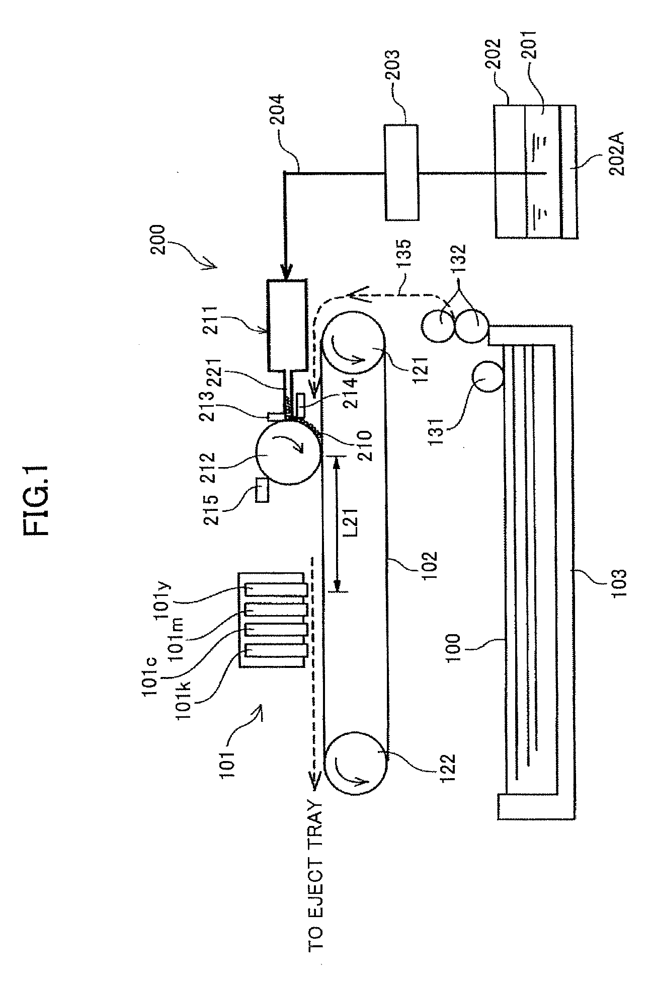
[0039]First, a description will be given of the image forming apparatus in the present invention, by referring to FIG. 1. FIG. 1 is a diagram showing a general structure of the image forming apparatus in this first embodiment of the present invention.

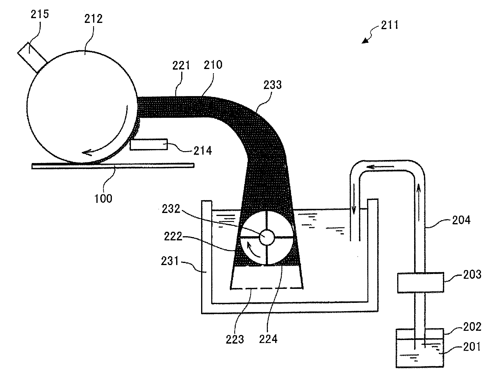
[0040]The image forming apparatus shown in FIG. 1 includes a recording head unit 101 for jetting ink (or ink drops) to form an image on recording medium 100 such as paper, a transport belt 102 for transporting the recording medium 100, a supply tray 103 for accommodating the recording media 100, and a foam coating apparatus 200 which will be described later. The foam coating apparatus 200 coats foam on the recording medium 100, which is a coating target member, on an upstream side of the recording head unit 101 in a transport direction of the recording medium 100.

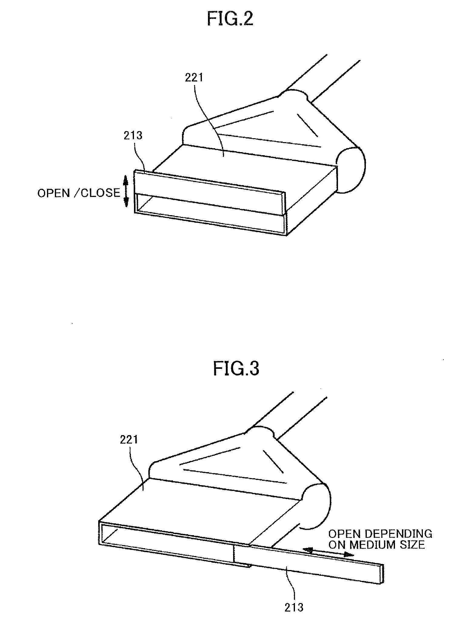
[0041]The recording head unit 101 is formed by a line type ink jet head having a plurality of nozzles for jetting the ink arranged in a line for a length amounting to the width...

second embodiment

[0095]Therefore, the size of the image forming apparatus can be reduced by setting the positional relationship between the coating roller 212 and the transport path which transports the recording medium 100 to the coating position of the coating roller 212 so that the coating position is located at a position other than below the coating roller 212 in the vertical direction. In this second embodiment, the positional relationship between the coating roller 212 and the transport path which transports the recording medium 100 to the coating position of the coating roller 212 is set so that the coating position is located above the coating roller 212 in the vertical direction.

[0096]The foam generating mechanism (or foam generating means) for generating the foam 210 in this second embodiment is not limited to that of the first embodiment which supplies the foam 210 by the accumulation force thereof. For example, a screw-like structure may be used to generate the foam (foam setting agent)...


PUM


Abstract

An image forming apparatus includes a generating mechanism to generate foam from a liquid or gel which may take a foam state, a coating roller having a peripheral surface supplied with the foam to coat the foam on the peripheral surface onto a surface of a recording medium, and a transport passage to transport the foam from the generating mechanism to the coating roller by an accumulation force of the foam.

Description

TECHNICAL FIELD[0001]The present invention generally relates to image forming apparatuses and apparatuses for coating foam on a coating target member, and more particularly to an image forming apparatus which coats foam on a recording medium on which a recording head forms an image by jetting ink on the recording medium, and to an apparatus which coats the foam on the coating target member.BACKGROUND ART[0002]A printer, a facsimile machine, a copying machine, a plotter, and a Multi-Function Peripheral (MFP) which combines the functions of two or more of such equipments, may have a recording head which is configured to form an image on a recording medium which is transported, by jetting ink on the recording medium. The recording medium may be formed by any suitable material or member capable of bearing the image thereon. Examples of the recording medium include a transfer member, recording paper, recording sheet and the like. In this specification, “forming the image on the recording...

Claims


Application Information

Patent Timeline
IPC IPC(8): B05C9/14B05C1/02B05C11/10B05C13/00
CPCB05C1/0813G03G15/1695B41J11/0015
Inventor ICHIMURA, MINORIKATO, YASUHISAMATSUMOTO, KAZUYOSHIIZUMIKAWA, MANABUKATANO, YASUO
Owner RICOH KK
Why Eureka
Try Eureka