Reflow apparatus

a reflow apparatus and reflow technology, applied in the direction of soldering apparatus, manufacturing tools, final product manufacturing, etc., can solve the problems of difficult control of conventional reflow apparatuses, difficult to precisely adjust the reflow peak time, etc., and achieve the effect of widening the temperature adjustment profil

Inactive Publication Date: 2010-09-02
TAMURA KK +1
View PDF22 Cites 9 Cited by
  • Summary
  • Abstract
  • Description
  • Claims
  • Application Information

AI Technical Summary

Benefits of technology

[0009]According to the invention, since a plurality of reflow zones that are formed shorter in length than the individual preheating zones of the preheating area in the work transfer direction are provided in the reflow area, it becomes possible to more precisely adjust the temperature profile, such as reflow peak time, etc., of a work that is subjected to heating in these reflow zones for reflow than in the conventional art, wherein components having weak heat resistance can be processed with the reflow peak time shortened by a compact temperature profile, on the other hand, it is possible to secure a reflow peak time necessary and sufficient to obtain a sufficient soldering connection, and various temperature profiles can be set. Further, various temperature profiles can be set without making a conventional apparatus large-sized, wherein a wide range of work characteristics can be processed.
[0010]According to another aspect of the invention, it becomes possible to further precisely adjust the temperature profile of the reflow area by individually controlling the temperature of three reflow zones, wherein the variation in the temperature adjustment profile can be widened.

Problems solved by technology

On the other hand, although it is necessary to more precisely control the heating temperature and heating time in order to secure heat resistance of components to be mounted on a substrate, which are heated for reflow, the control is difficult by conventional reflow apparatuses, wherein particularly there is a problem that it is not easy to precisely adjust the reflow peak time.

Method used


Image

  • Reflow apparatus
  • Reflow apparatus
  • Reflow apparatus

Examples


Embodiment Construction

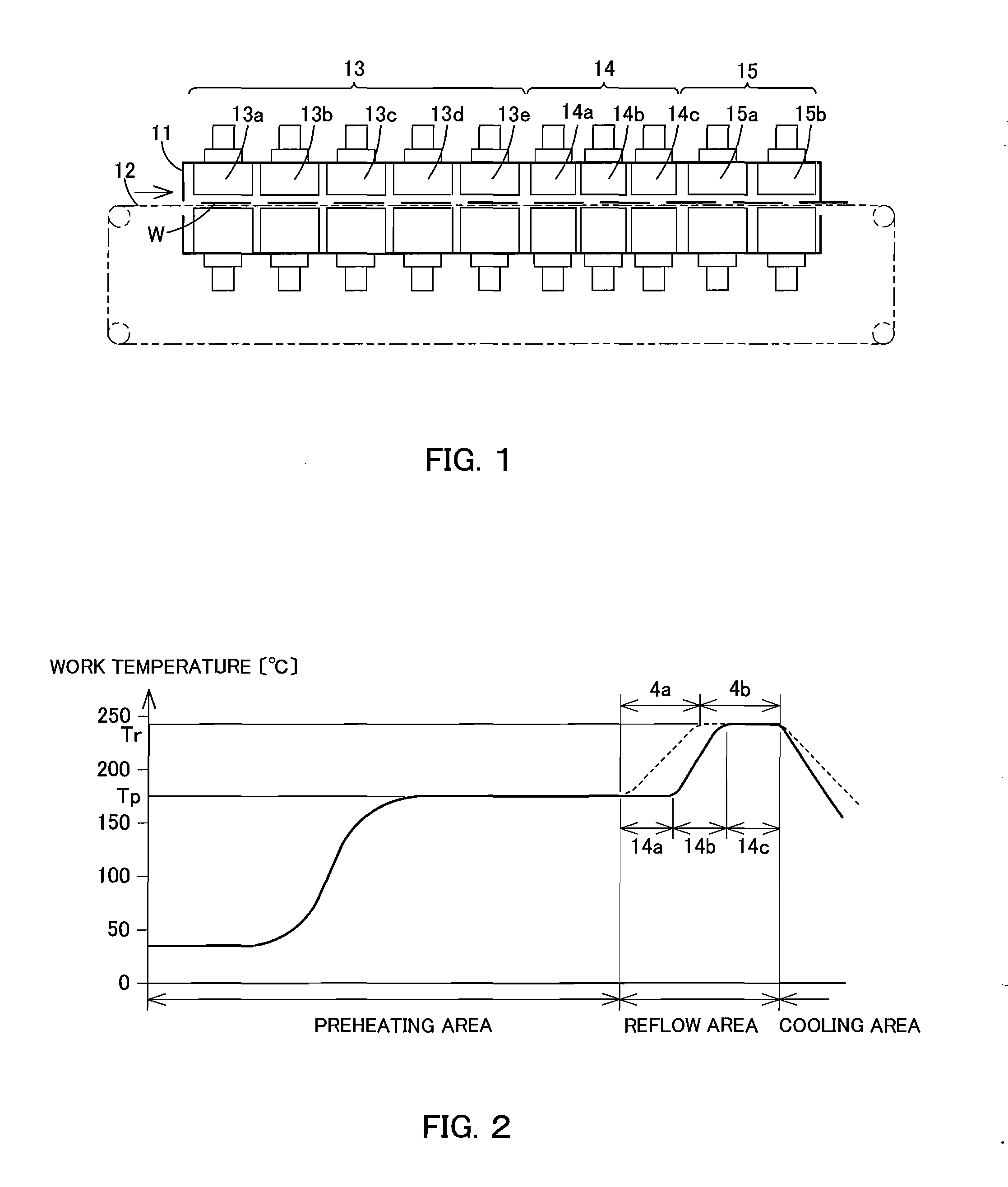
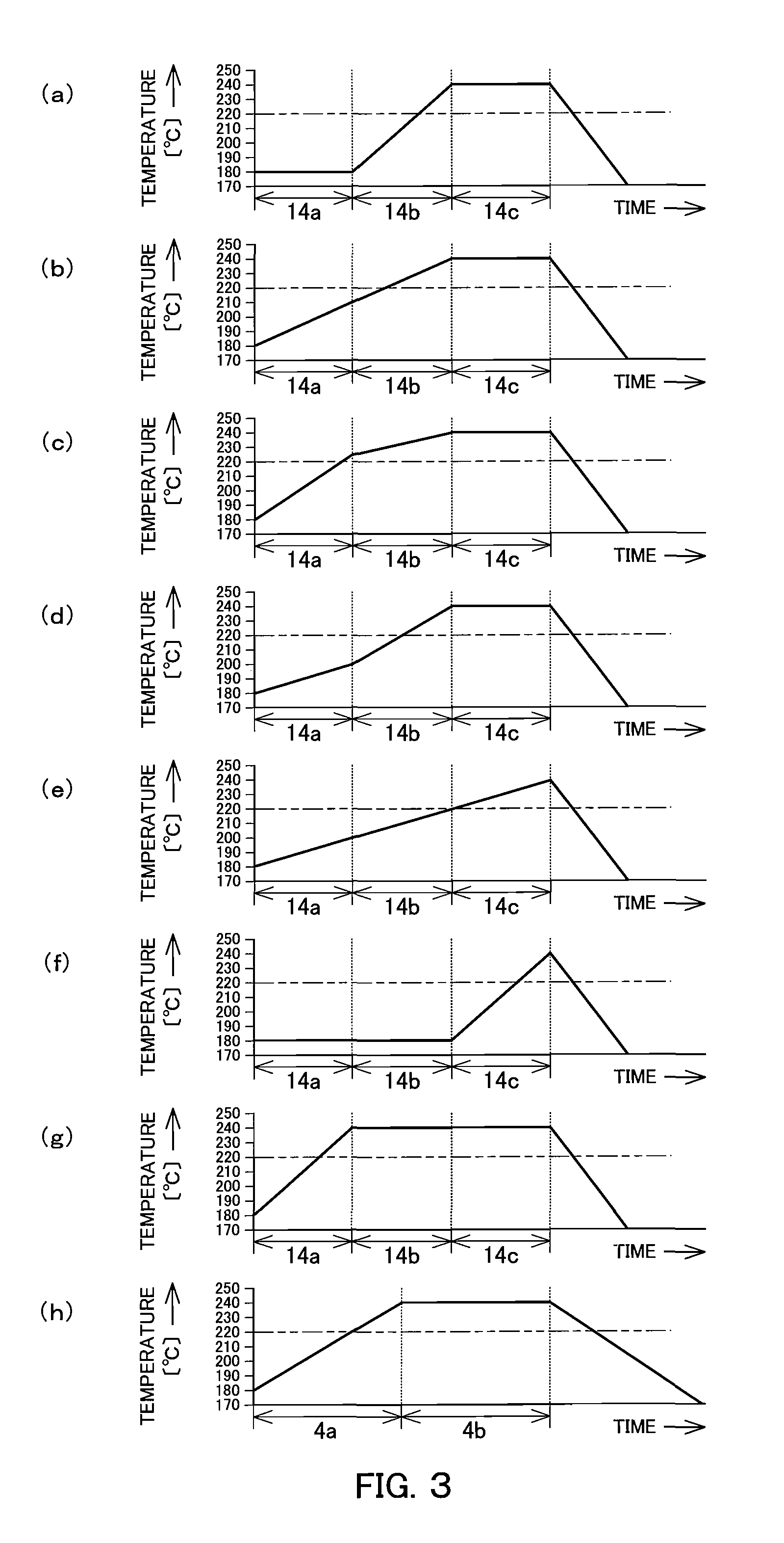
[0016]Hereinafter, a detailed description is given of the present invention with reference to FIG. 1 through FIG. 3.

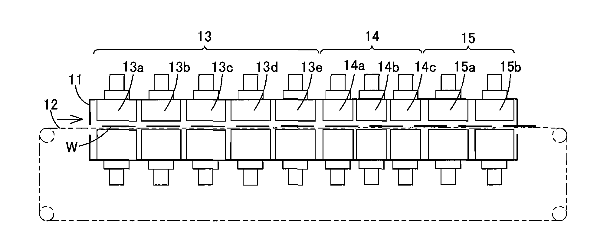
[0017]FIG. 1 shows a reflow apparatus. A work transfer conveyor 12 for transferring a work W into the furnace body 11 is disposed. A preheating area 13 having a plurality of preheating zones 13a, 13b, 13c, 13d, and 13e (hereinafter, these reference numerals are described to be 13a through 13e) for preheating a work W, a reflow area 14 having a plurality of reflow zones 14a, 14b and 14c for heating the work W for reflow, and a cooling area 15 having a plurality of cooling zones 15a and 15b for cooling the work W are successively arranged along the work transfer conveyor 12 in the furnace body 11.

[0018]A heating unit having a blower and a structure, which circulate the atmospheric air, a heater for heating the atmospheric air, a nozzle for jetting hot air, and a temperature sensor for detecting a hot air temperature is disposed at the respective preheating zones 13a thro...


PUM

PropertyMeasurementUnit
melting temperatureaaaaaaaaaa
temperatureaaaaaaaaaa

Abstract

The present invention provides a reflow apparatus capable of precisely adjusting the heating temperature and heating time when heating a work for reflow. A work transfer conveyor for transferring a work into a furnace body is disposed, wherein a plurality of preheating zones through for preheating the work, a plurality of reflow zones for heating the work for reflow, and a plurality of cooling zones for cooling the work are successively arranged along the work transfer conveyor in the furnace body. The individual reflow zones are formed shorter than the individual preheating zones in the work transfer direction. It is preferable that the sizes of the individual reflow zones in the transfer direction are shortened to approximately 65% to 85% with respect to the individual preheating zones or the conventional individual reflow zones.

Description

CROSS REFERENCE TO RELATED APPLICATIONS[0001]This is a U.S. national phase application under 35 U.S.C. §371 of International Patent Application No. PCT / JP2006 / 325263, filed Dec. 19, 2006 and claims the benefit of Japanese Application No. 2006-001782, filed Jan. 6, 2006. The International Application was published in Japanese on Jul. 12, 2007 as International Publication No. WO 2007 / 077727 under PCT Article 21(2) the contents of which are incorporated herein in their entirety.TECHNICAL FIELD[0002]The present invention relates to a reflow apparatus used in heating for reflow.BACKGROUND ART[0003]As shown in FIG. 5, a reflow apparatus has a preheating area 3 including a plurality of preheating zones 3a, 3b, 3c, 3d and 3e for preheating a work W, a reflow area 4 including a plurality of reflow zones 4a and 4b for heating the work W for reflow, and a cooling zone 5 for cooling the work W, all of which are successively arranged in a furnace body 1 along a work transfer conveyor 2 for trans...

Claims


Application Information

Patent Timeline
Patent Type & Authority Applications(United States)
IPC IPC(8): B23K3/04
CPCB23K1/008H05K3/3442H05K2203/111H05K2201/10636H05K3/3494Y02P70/50
Inventor YAMASHITA, FUMIHIROMATSUHISA, SHOICHIROKAWAKAMI, TAKEHIKO
Owner TAMURA KK
Why Eureka
Try Eureka