
Method and device for controlling the operation of power at the point of maximum power

a power supply and maximum power technology, applied in the field of supply systems, can solve the problems of hardware support, increased direct cost, greater burden, etc., and achieve the effect of low cost, economic efficiency, and maximizing both power efficiency

Inactive Publication Date: 2010-09-02
UNIV DEGLI STUDI DI PARMA
View PDF1 Cites 23 Cited by
  • Summary
  • Abstract
  • Description
  • Claims
  • Application Information

AI Technical Summary

Benefits of technology

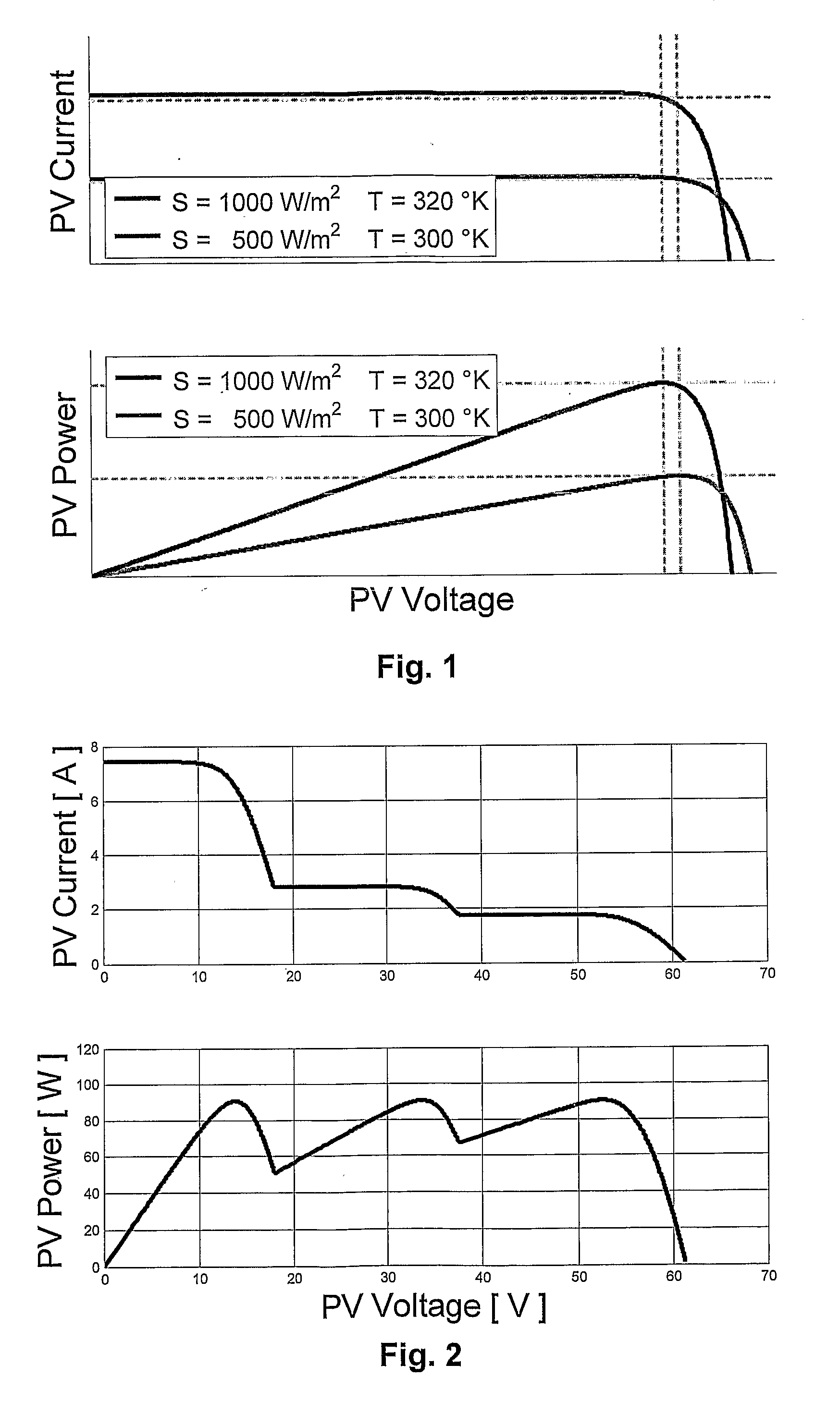
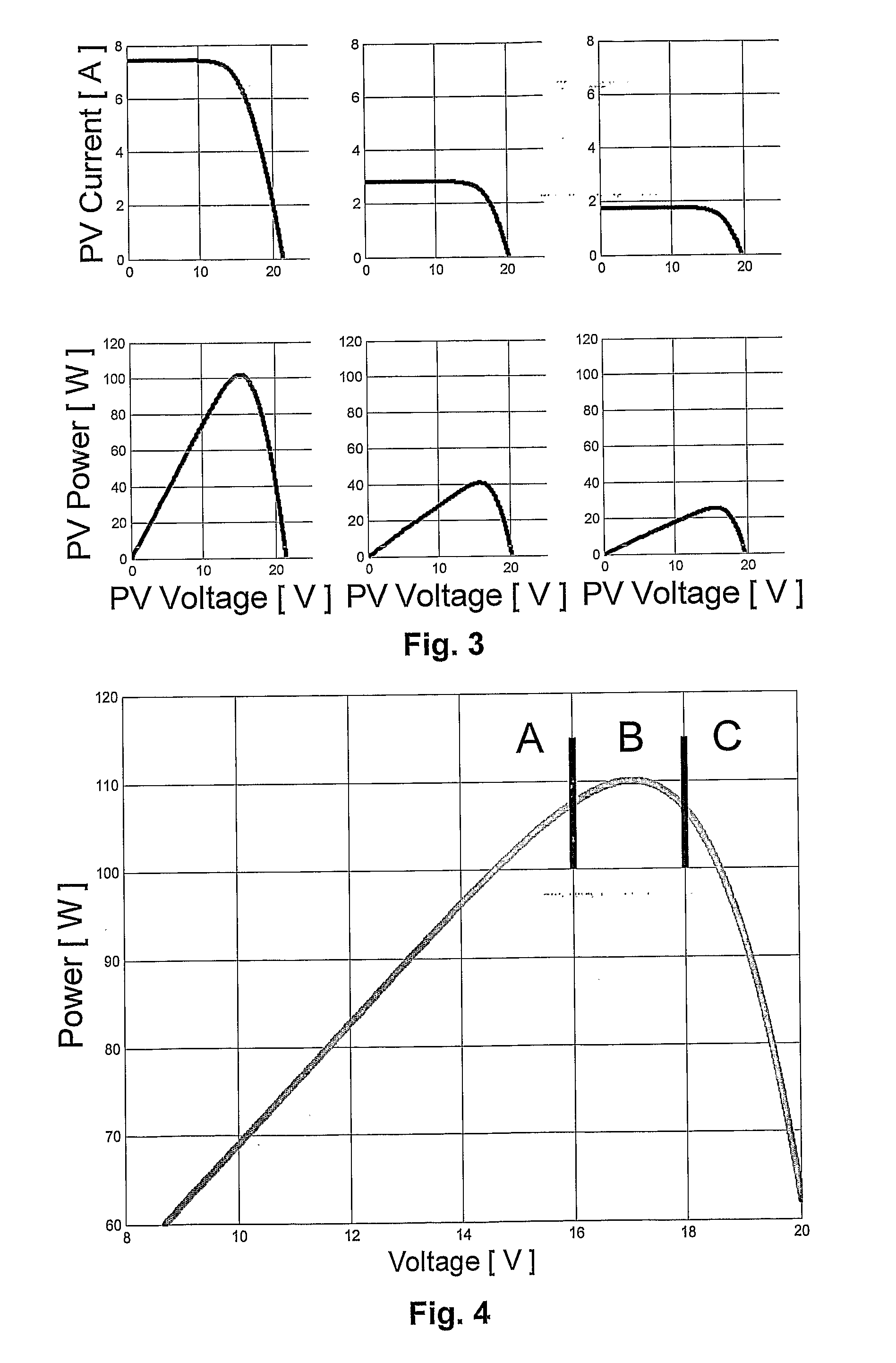
[0054]The purpose of the present invention is a control method, and the corresponding circuit architecture, for a supply system that enables extraction of the maximum power that can be delivered by sources of any kind constituted by one or more power modules each characterized by a maximum power, point and / or characterized by the presence of a local maximum on the curve of the power as a function of the voltage at the connection terminals, which is able to solve Equation (1) and is implemented at low cost with a minimum number of discrete analog devices and integrated analog devices of a widely used type.
[0055]With reference to the applications for renewable power sources, in particular photovoltaic sources, the present invention guarantees modularization of the function of extraction of the maximum power of the photovoltaic field, maximizing both the power efficiency (enabling connections in series and / or in parallel of non-homogeneous photovoltaic; panels of low nominal power (50-200 Wp), each of which operating in its own MPP) and the economic efficiency. Furthermore, said solution is proposable for systems of low nominal power (200-1000 Wp), generated by a single photovoltaic module or a limited number of photovoltaic modules, comprising supply units obtained with DC / DC switching converters. Furthermore, said solution is proposable as input stage of an inverter of average nominal power (1-20 kWp), which is able to supply at its output terminals an a.c. voltage both, for stand-alone systems and for grid-connected systems.

Problems solved by technology

A first disadvantage lies in the fact that, in addition to a microcontroller, there are also required: analog-to-digital conversion modules; memory modules; digital-to-analog conversion modules; and further supporting hardware.
In addition to the higher direct cost, the indirect costs due to the greater encumbrance and the higher consumption are also to be considered.
Another evident disadvantage is the low speed at which the system responds for adapting the operating point, which is not compatible with an adequate level of performance required.
Furthermore said solution is more sensitive to noise and to errors of measurement and quantization of the voltage, current, and power sensors.

Method used


Image

  • Method and device for controlling the operation of power at the point of maximum power
  • Method and device for controlling the operation of power at the point of maximum power
  • Method and device for controlling the operation of power at the point of maximum power

Examples


Embodiment Construction

[0056]The following description represents an example of the application of the invention to a maximum-power-point tracker of a solar generator. As mentioned previously, this represents an example of source characterized by the presence of an absolute maximum on the curve of the power as a function of the voltage at its own terminals.

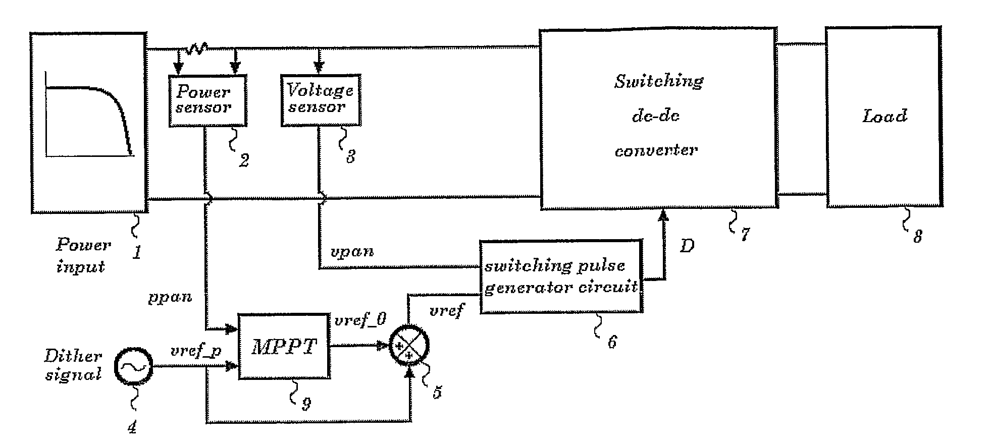
[0057]FIG. 7 illustrates a block diagram of the device according to the present invention. In FIG. 7:[0058]the reference number 1 designates the photovoltaic field, defined as a single photovoltaic module or else a set of two or more photovoltaic modules connected in series and / or in parallel;[0059]the reference numbers 2 and 3 designate the power sensor ppan and voltage sensor vpan, respectively;[0060]the reference number 4 designates the generator of the perturbing signal Vref—p(t)=Vref—p·cos(2πfp·t);[0061]said signal cannot be present in systems that use as perturbing signal any intrinsic oscillation of the system not attenuated by the control networ...


PUM


Abstract

A control method and a control device for controlling a supply unit, which enable supply of the maximum power that can be delivered by a power source, the method includes the presence of an absolute maximum on the curve of the power as a function of the voltage at the connection terminals; the supply system set between the power source and the load is preferably a DC / DC switching converter. The control circuit identifies the optimal operating point, using the relation existing between the harmonic components of the power and the harmonic components of the voltage at the terminals of the source. Starting from any value of the voltage at the connection terminals, the control circuit increments the value of the voltage if, for a given value of the frequency, the power and the voltage at the connection terminals are in phase, whilst it decrements the value of the voltage if the power and the voltage are in phase opposition.

Description

TECHNICAL FIELD OF THE INVENTION[0001]The present invention relates to systems for supply from autonomous electric-power sources, and more precisely to operation and control of supply systems, in which the power source is characterized by the presence of an absolute maximum on the curve of the power as a function of the voltage at its own terminals.[0002]For the aforesaid kind of sources, the power that can be delivered is maximum at a given optimal voltage value. For optimal operation of the supply system, corresponding to supply of the maximum power that can be delivered, it is necessary for the voltage at the terminals of the source to be as close as possible to the optimal voltage value referred to. For this purpose, generally set between the source and the load is an appropriately controlled DC / DC converter. The control circuits and algorithms that are able to guarantee, instantaneously and continuously, an accurate tracking of the optimal operating point are defined by the ter...

Claims


Application Information

Patent Timeline
IPC IPC(8): H02J4/00G05F1/70
CPCH02M3/157G05F1/67
Inventor FEMIA, NICOLADE ROSA, FILIPPOSIRIANNI, ANTONIOPETRONE, GIOVANNIEGIZIANO, LUIGISPAGNUOLO, GIOVANNIVITELLI, MASSIMO
Owner UNIV DEGLI STUDI DI PARMA
Learn More