Electric motor

a technology of electric motors and motors, applied in the direction of electronic commutators, synchronous motor starters, modelling/simulation of control, etc., can solve the problems of low power reserve at high outside, and the inability to operate the motor at all

Active Publication Date: 2010-09-02
EBM PAPST ST GEORGEN & -
View PDF6 Cites 7 Cited by
  • Summary
  • Abstract
  • Description
  • Claims
  • Application Information

AI Technical Summary

Benefits of technology

[0004]It is therefore an object of the invention to make availab...

Problems solved by technology

Because of the heat generated in the internal power stage of this module, such modules have the disadvantage that they have little power res...

Method used


Image

  • Electric motor
  • Electric motor
  • Electric motor

Examples


Embodiment Construction

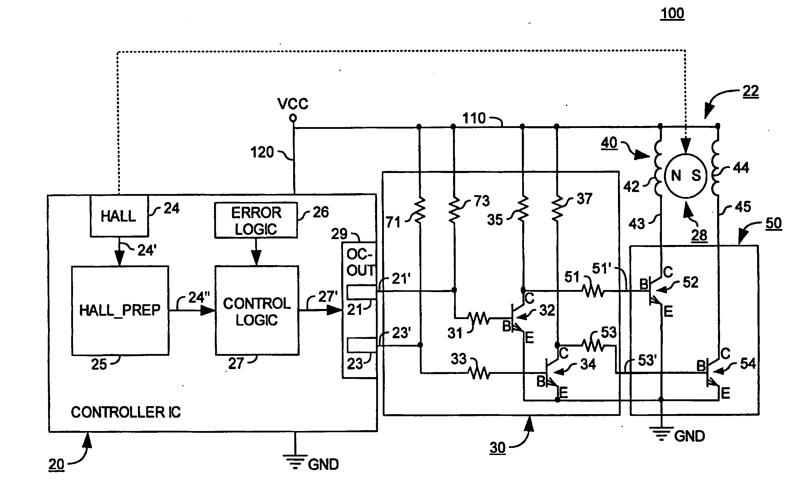
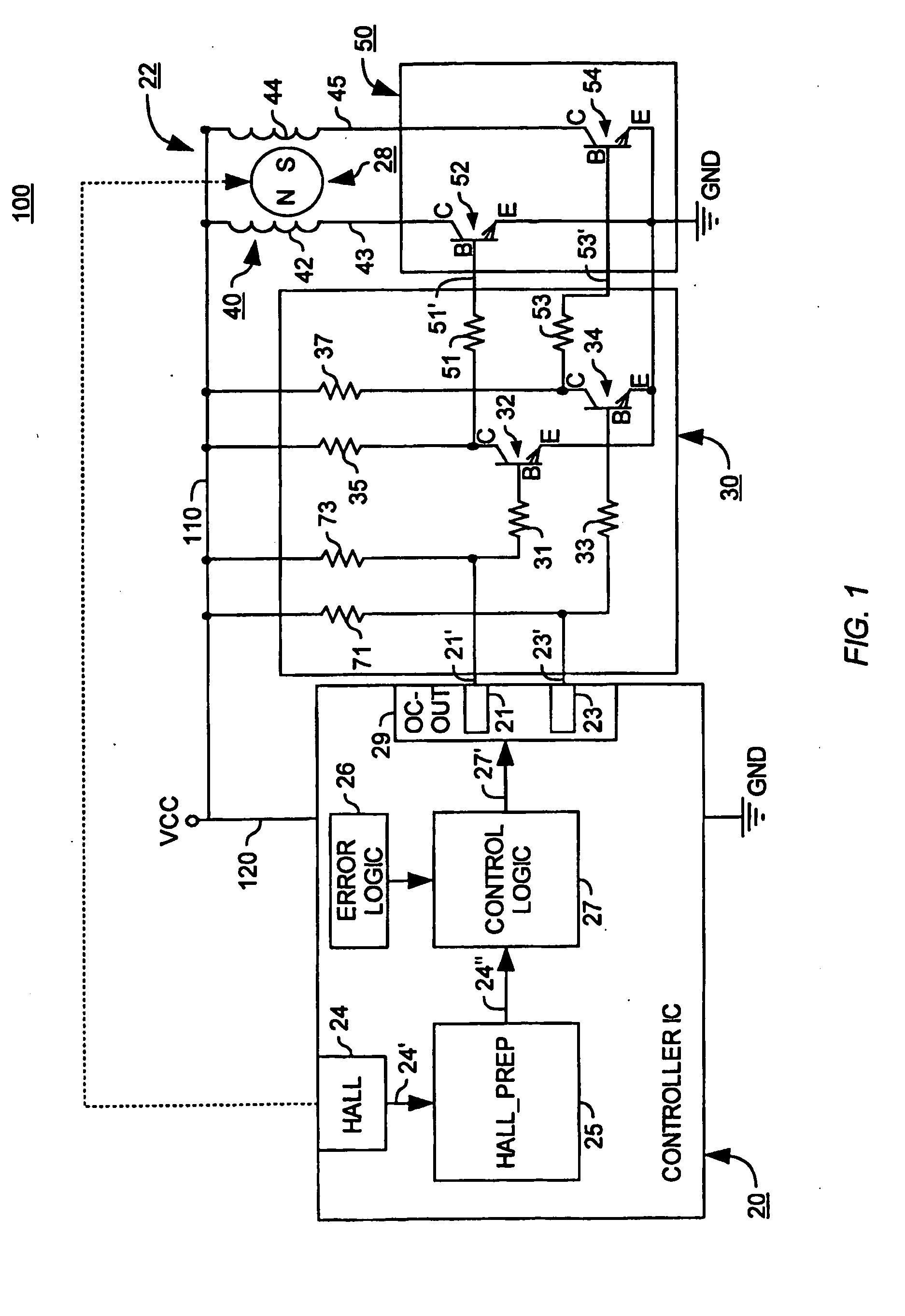
[0013]In the description that follows, identical or identically functioning parts are labeled with the same reference characters in the various Figures, and usually are described only once.

[0014]FIG. 1 is a circuit diagram of an apparatus 100 for operating an ECM 22, which latter has a permanent-magnet rotor 28 and a stator winding arrangement 40. The latter is depicted, by way of example, in two-stranded fashion, i.e. having two winding strands 42, 44. These are connected on the one hand via a supply lead 110 to a DC voltage source VCC, and on the other hand to an external power stage 50. Voltage source VCC is connected via a supply lead 120 to a motor control module 20 (CONTROLLER IC). The ends of strands 42, 44 connected to supply lead 110 are referred to hereinafter as “upper” ends, whereas the ends connected to external power stage 50 are referred to as “lower” ends 43, 45.

[0015]External power stage 50 serves to influence the currents in winding strands 42, 44, and has two semi...


PUM


Abstract

An electronically commutated electric motor (110) has a permanent-magnet rotor (28), a stator having a stator winding arrangement (40), a motor control module (20) implemented as an IC and having a control logic unit (27), and an external power stage (50), separate from the IC, for influencing the current flow in the stator winding arrangement (40). The motor control module (20) has an internal power stage (29) having at least one open collector output (21, 23). The control logic unit (27) is configured to process a rotor position signal (24′, 24″) and to generate therefrom control signals (27′) for the internal power stage (29), which control signals (27′) serve to apply control to the internal power stage (29). Using an external power stage (50) reduces vulnerability to motor overheating and provides design flexibility.

Description

CROSS-REFERENCE[0001]This application is a section 371 of PCT / EP2007 / 02434 filed 20 Mar. 2007 and published as WO 2007-140832-A1 on 13 Dec. 2007.FIELD OF THE INVENTION[0002]The present invention relates to an electronically commutated motor (ECM) which has reduced vulnerability to overheating.BACKGROUND[0003]Integrated motor control modules exist that have an internal power stage for direct connection of at least one stator strand of an ECM. Because of the heat generated in the internal power stage of this module, such modules have the disadvantage that they have little power reserve at high outside temperatures, i.e. they then enable only a low motor power level, or operation of the motor is then no longer possible at all. This is referred to as “derating,” i.e. the maximum power output or “rating” depends on the ambient temperature of the motor module, and decreases or becomes more or less limited with increasing temperature.SUMMARY OF THE INVENTION[0004]It is therefore an object ...

Claims


Application Information

Patent Timeline
IPC IPC(8): H02P6/14
CPCH02P6/001H03K17/687H03K17/64H03K17/603H02P6/34
Inventor ZIPSER, THOMASLOFFLER, JENS
Owner EBM PAPST ST GEORGEN & -
Why Eureka
Try Eureka