Magnetic Field Detection Apparatus and Measurement Apparatus

a detection apparatus and magnetic field technology, applied in the field of magnetic field detection apparatus, can solve the problems of change in measurement errors, inability to meet v=0, so as to accurately measure the physical quantities of the environment, and accurately measure the direction of magnetic field.

Active Publication Date: 2010-09-02
HITACHI LTD
View PDF17 Cites 30 Cited by
  • Summary
  • Abstract
  • Description
  • Claims
  • Application Information

AI Technical Summary

Benefits of technology

[0031]As described above, according to the present invention, it is possible to eliminate an offset voltage generated at a signal voltage of a Wheatstone bridge resulting from property deviation of magneto-resistive elements (MR elements). Accordingly, it becomes possible to accurately measure the direction of a magnetic field with a magnetic field detection apparatus having magneto-resistive elements.
[0032]It becomes also possible to suppress, even when the ambient temperature of the magnetic field detection apparat

Problems solved by technology

In practice, however, there are cases in which Δv=0 cannot be satisfied and an offset voltage remains even when θ=90°.
Since the angle θ of a magnetic field is calculated on the assumption that the signal Δv is proportional to cos θ, measurement errors could occur if an offset voltage remains.
Further, since an offset voltage changes with temperature in many cases, a change in temperature could also result in a change in measurement errors.
This method, however, has a problem in that since an offset voltage could change with a ch

Method used


Image

  • Magnetic Field Detection Apparatus and Measurement Apparatus
  • Magnetic Field Detection Apparatus and Measurement Apparatus
  • Magnetic Field Detection Apparatus and Measurement Apparatus

Examples


embodiment 1

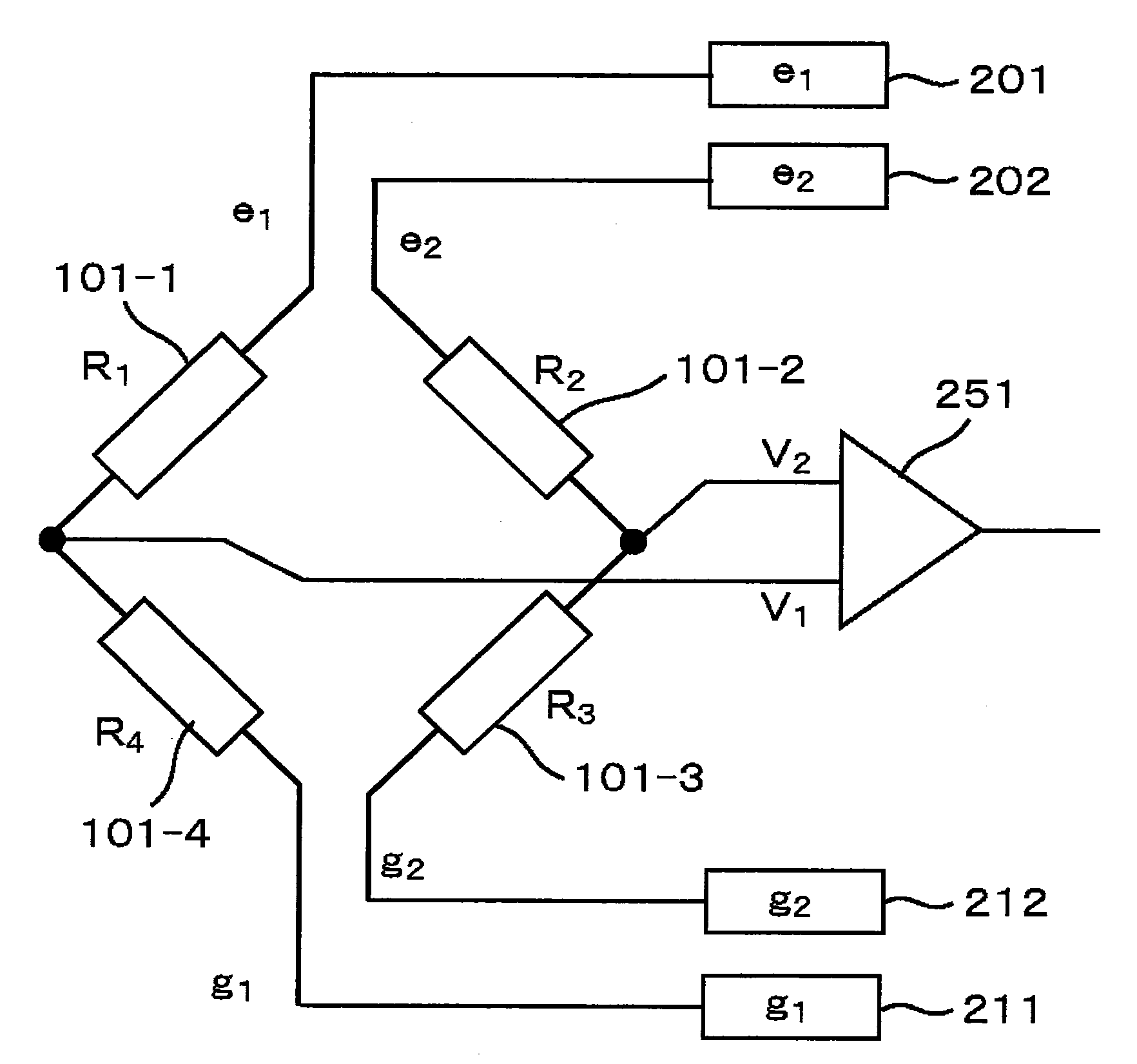
[0110]FIG. 1 is a schematic diagram showing the configuration of a magnetic field detection apparatus of the first embodiment.

[0111]The magnetic field detection apparatus of the present embodiment includes four GMR elements 101-1, 101-2, 101-3, and 101-4. FIG. 1 shows a method of connecting such elements.

[0112]A half-bridge having the GMR elements 101-1 and 101-4 is connected to a positive-polarity output circuit e1(201) and a negative-polarity output circuit g1(211). A connection node of the GMR elements 101-1 and 101-4 is a signal terminal V1.

[0113]A half-bridge having the GMR elements 101-2 and 101-3 is connected to a positive-polarity output circuit e2(202) and a negative-polarity output circuit g2(212). A connection node of the GMR elements 101-2 and 101-3 is a signal terminal V2.

[0114]The signal terminal V1 and the signal terminal V2 are connected to a detection circuit (hereinafter also referred to as a “differential amplifier” or a “differential detector”) 251 which detects ...

embodiment 2

[0154]A rotation angle detection apparatus will now be described as a second embodiment of the present invention.

[0155]FIG. 6 is a schematic diagram showing the structure of the second embodiment of the present invention. A stator unit includes a flat-plate supporting unit 503 made of a non-magnetic material and a magnetic field detection apparatus 502 disposed on the upper surface of the supporting unit.

[0156]A rotor unit includes a rotation axis 504 made of a non-magnetic material and a magnet 505 integrally secured to the rotation axis. The rotation axis is rotatably supported by a stationary case (not shown) such that it faces the stator unit with a predetermined gap therebetween. The magnet 505 is a disk-shaped magnet made of ferrite or the like, and has an N pole and a S pole that are magnetized so as to form a uniform magnetic field 506 above the magnetic field detection apparatus 502 of the stator unit.

[0157]For the magnetic field detection apparatus 502, a magnetic field de...

embodiment 3

[0160]A rotation angle detection apparatus will now be described as the third embodiment of the present invention.

[0161]In the present embodiment, the rotation angle is detected using only a COS bridge. Although the structure of the present embodiment is similar to that shown in FIG. 6, the magnetic field detection apparatus 502 of FIG. 6 includes only a COS bridge. The COS bridge has the configuration described in Embodiment 1.

[0162]FIG. 7 schematically shows a view in which the output signal Δv(cos) of the COS bridge of the magnetic field detection apparatus 502 changes with the rotation angle θ. As seen from Formula 17, the Δv(cos) signal is proportional to cos θ, as depicted with the solid line in FIG. 7. A waveform of the dotted line in FIG. 7 schematically shows the waveform of an output signal at a different temperature. Although a signal proportional to cos θ is obtained, the amplitude differs. This is because the constant C of proportionality of Formula 17 changes with temp...


PUM


Abstract

There has been a problem that a bridge circuit using magneto-resistive elements or transducer elements could output a signal including an offset voltage, which could result in lower measurement accuracy. In order to solve such a problem, half-bridges each having magneto-resistive elements or transducer elements are excited with different excitation voltages so that the offset voltage is eliminated and the measurement accuracy is improved.

Description

BACKGROUND OF THE INVENTION[0001]1. Field of the Invention[0002]The present invention relates to a magnetic field detection apparatus that detects the angle and intensity of a magnetic field using magneto-resistive elements (hereinafter also referred to as MR (magnetoresistive) elements). The present invention also relates to an apparatus for measuring displacement that measures displacement of physical quantity such as displacement of an angle, gradient, or stroke using magneto-resistive elements (hereinafter also referred to as MR (magnetoresistive) elements). Further, the present invention also relates to a measurement apparatus using transducer elements whose resistance changes depending on the ambient physical quantity.[0003]2. Background Art[0004]Such a magnetic field detection apparatus or an apparatus for measuring displacement using MR elements has been known from, for example, Reference 1 (JP Patent Publication (Kokai) No. 2003-121197 A), Reference 2 (JP Patent Publication...

Claims


Application Information

Patent Timeline
IPC IPC(8): G01R33/02G01R33/00
CPCG01D1/00G01R33/091G01D21/00G01D15/00
Inventor SUZUKI, MUTSUMIKANEKAWA, NOBUYASUYAMADA, MASAMICHI
Owner HITACHI LTD
Why Eureka
Try Eureka