Stereoscopic image display apparatus

Inactive Publication Date: 2010-09-02
3DIS
View PDF8 Cites 4 Cited by
  • Summary
  • Abstract
  • Description
  • Claims
  • Application Information

AI Technical Summary

Benefits of technology

[0038]The invention is contrived to solve the above-mentioned problems. A goal of the invention is to provide a stereoscopic image display apparatus employing a front type parallax barrier which can reduce a visible distance.

Problems solved by technology

The method using the polarizing spectacles is not widely used in stereoscopic image display apparatuses because of inconvenience resulting from the ware of spectacles and dangerousness of opthalmology diseases.
Since the lenticular method and the holographic method have complicated structures and require high cost, they are used for only particular applications.
The past rear type parallax-barrier stereoscopic image display apparatus has problems with low brightness, complicated manufacturing processes, high cost, and the like.
However, the front type parallax-barrier stereoscopic image display apparatuses have a problem with a large visible distance (distance where a stereoscopic image is visible).
For this reason, the front type parallax-barrier stereoscopic image display apparatuses were not commercialized, in spite of their merits of simple manufacturing processes and high brightness.
However, when the front type parallax-barrier stereoscopic image display apparatus is applied to a computer monitor, the visible distance of 1.2 m causes a serious problem.
When the front type parallax-barrier stereoscopic image display apparatus is applied to a mobile terminal such as a mobile phone or a PDA, the visible distance of 1.2 m also causes a serious problem.
That is, it is not possible to enjoy a stereoscopic game service or confirm stereoscopic image information at the same time of recognizing a stereoscopic image by the use of a mobile terminal.
Since the screen of the mobile terminal is small, it is not possible to recognize an image by employing the front type parallax-barrier stereoscopic image display apparatus.
Accordingly, even when a diamond zone (which is described later) of 40 to 90 cm of a mobile terminal is considered, it is not possible to view a desired stereoscopic image by the use of the known front type parallax-barrier stereoscopic image display apparatus.

Method used


Image

  • Stereoscopic image display apparatus
  • Stereoscopic image display apparatus
  • Stereoscopic image display apparatus

Examples


Embodiment Construction

[0049]Hereinafter, a stereoscopic image display apparatus according to an embodiment of the invention will be described in detail with reference to the accompanying drawings.

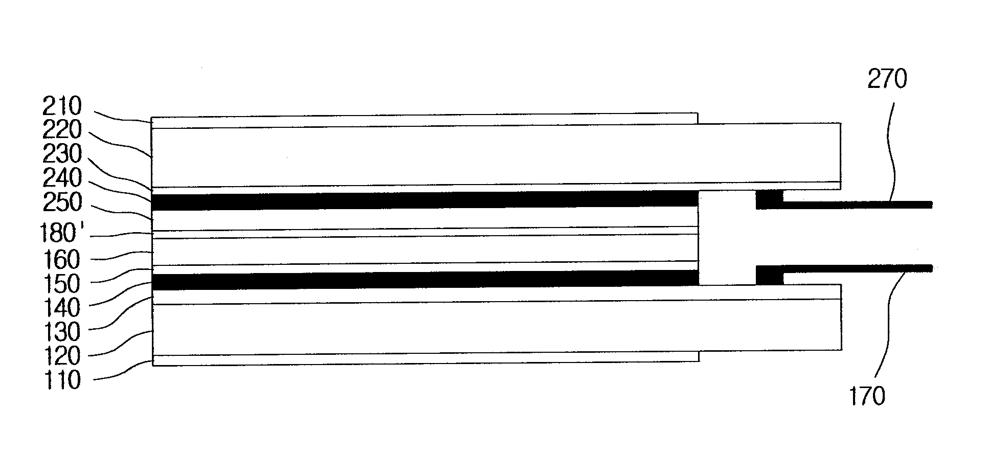
[0050]FIG. 4 is a sectional view schematically illustrating a stereoscopic image display apparatus according to an embodiment of the invention. In the stereoscopic image display apparatus, a parallax barrier liquid crystal display (LCD) panel is disposed in the front of a 2D image LCD panel. The stereoscopic image display apparatus having such a structure is called a front type parallax-barrier stereoscopic image display apparatus.

[0051]The 2D image LCD panel includes a first substrate 120 in which a rear polarizing film 110 is stacked at least on the rear surface thereof and a first switching element layer 130 is stacked on the front surface thereof, a second substrate 220 having a color filter layer 150 stacked thereon, and a first liquid crystal layer 140 interposed between the first switching element layer 1...


PUM


Abstract

A stereoscopic image display apparatus employing a front type parallax barrier is provided which can reduce a visible distance. The stereoscopic image display apparatus includes: a 2D image LCD panel having a first substrate in which a rear polarizing film is stacked on the rear surface thereof and a first switching element layer is stacked on the front surface thereof, a second substrate on which a color filter layer is stacked, and a first liquid crystal layer interposed between the first switching element layer and the color filter layer; a parallax barrier having a third substrate in which a front polarizing film is stacked on the front surface thereof and a transparent electrode layer is stacked on the rear surface thereof, a protective film, and a second liquid crystal layer interposed between the transparent electrode layer and the protective film; and an intermediate polarizing film interposed between the protective film of the parallax barrier and the second substrate of the 2D image LCD panel.

Description

TECHNICAL FIELD[0001]The present invention relates to a stereoscopic image display apparatus, and more particularly, to a stereoscopic image display apparatus employing a front type parallax barrier which can reduce a visible distance.BACKGROUND ART[0002]Methods of displaying a stereoscopic image include a method using polarizing spectacles and a method not using polarizing spectacles. The method using the polarizing spectacles is not widely used in stereoscopic image display apparatuses because of inconvenience resulting from the ware of spectacles and dangerousness of opthalmology diseases. The method not using the polarizing spectacles is classified into a lenticular method, a holographic method, and a parallax barrier method. Since the lenticular method and the holographic method have complicated structures and require high cost, they are used for only particular applications. The parallax barrier method has been most actively studied, developed, and commercialized.[0003]The pri...

Claims


Application Information

Patent Timeline
IPC IPC(8): G02B27/26G02F1/1335G02B30/25G02B30/31
CPCG02B27/2214G02B30/31B21D43/285B21D43/13G02B30/27
Inventor PARK, IN-KYU
Owner 3DIS
Why Eureka
Try Eureka