LED light tube

Inactive Publication Date: 2010-09-02
LEDTECH ELECTRONICS CORP
View PDF6 Cites 47 Cited by
  • Summary
  • Abstract
  • Description
  • Claims
  • Application Information

AI Technical Summary

Benefits of technology

[0009]Therefore it is a primary object of the present invention to provide a LED light tube in which a tube-shaped heat dissipation base is disposed with a plurality of heat dis

Problems solved by technology

Moreover, the LED features on long life, low power consumption and lack of heat radiation.
However, LED has an overheating problem.
Once LED overheats, it dims with reduced light emitting effic

Method used


Image

  • LED light tube
  • LED light tube
  • LED light tube

Examples


Embodiment Construction

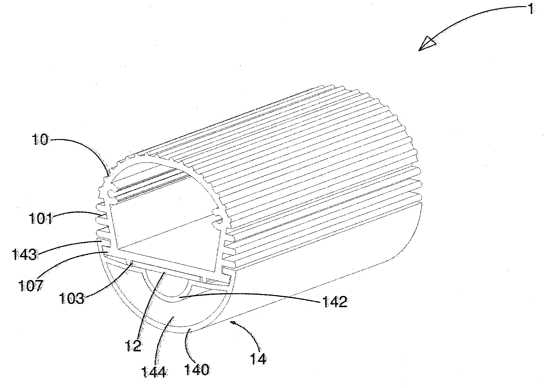
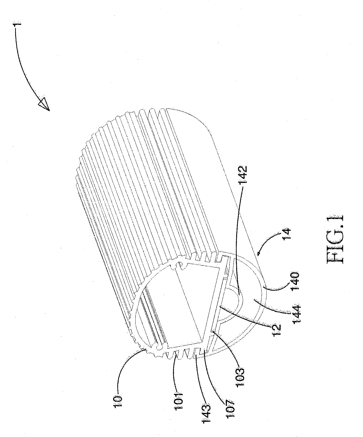
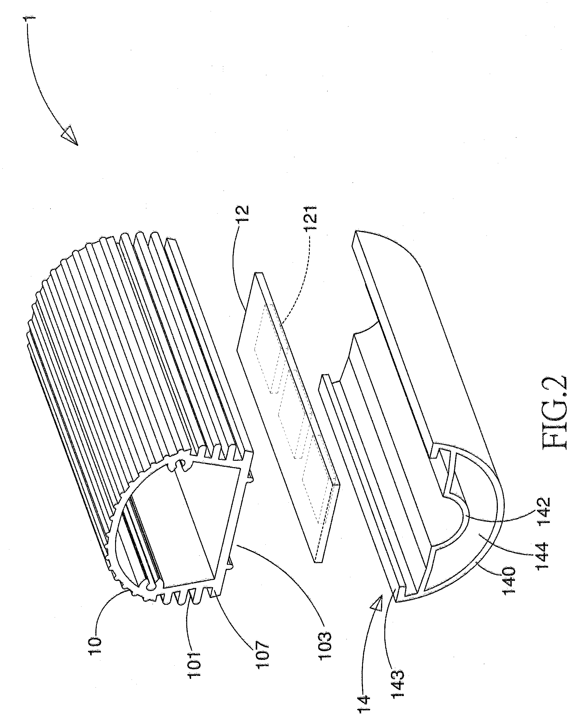
[0021]Refer to FIG. 1 and FIG. 2, a perspective view and an explosive view of an embodiment according to the present invention are revealed. As shown in figures, a LED light tube 1 provided by the present invention includes a tube-shaped heat dissipation base 10, a printed circuit board 12 and a light cover 14. The tube-shaped heat dissipation base 10 is a hollow tube made from metal for transferring heat. A plurality of heat dissipation fins 101 and a concave part 103 respectively for heat dissipation and for disposition of the printed circuit board 12 are arranged on a surface of the tube-shaped heat dissipation base 10. A first fix member 107 for fixing is disposed on each of two sides of the tube-shaped heat dissipation base 10. The printed circuit board 12 with a plurality of light emitting diodes 121 is arranged at the concave part 13 on the tube-shaped heat dissipation base 10. The light cover 14 consists of an outer light emitting layer 140 and an inner light emitting layer ...


PUM


Abstract

A LED light tube is revealed. The LED light tube includes a tube-shaped heat dissipation base, a printed circuit board and a light cover. The light cover includes an outer light emitting layer, an inner light emitting layer and a hollow part formed by a gap between the inner light emitting layer and the outer light emitting layer. The inner light emitting layer of the light cover presses on the printed circuit board in order to fix the printed circuit board on the tube-shaped heat dissipation base so that there is no need to use any other components for fixing the printed circuit board on the tube-shaped heat dissipation base.

Description

BACKGROUND OF THE INVENTION[0001]1. Fields of the invention[0002]The present invention relates to a light tube, especially to a light emitting diode (LED) light tube.[0003]2. Descriptions of Related Art[0004]Along with the increasing of the living standard, lamps and decorative lighting have received more attention. Once the proper decorative lighting is applied to exterior or interior decoration, it provides not only practical utility but also environment beautification. Now the most common light source for decorative lighting is fluorescent lamp.[0005]A fluorescent lamp is a gas-discharge lamp that uses electricity to excite mercury vapor. The lamp is filled with a gas containing mercury vapor formed by a few drops of mercury and argon. The pressure inside the lamp is around 0.3% of atmospheric pressure and mercury atoms are about one thousandth of the whole gas atoms. By applying current, the gas is excited to produce light. After long term use, dark marks are formed at the lamp ...

Claims


Application Information

Patent Timeline
IPC IPC(8): F21V1/00F21S4/00
CPCF21K9/00F21Y2101/02F21K9/17F21V29/77F21V29/507F21V29/75F21V29/76F21Y2103/003F21Y2103/10F21Y2115/10F21K9/66F21K9/275F21K9/27
Inventor KUO, CHENG-HSIUNGCHEN, HSUAN-HUI
Owner LEDTECH ELECTRONICS CORP
Why Eureka
Try Eureka