Isolating self-oscillation flyback converter

a self-oscillation and converter technology, applied in the direction of dc-dc conversion, power conversion systems, instruments, etc., can solve the problems of many problems and difficulties in practice, and achieve the effect of improving the production complexity of the transformer and simplifying the winding structur

Inactive Publication Date: 2010-09-02
MORNSUN GUANGZHOU SCI & TECH
View PDF3 Cites 3 Cited by
  • Summary
  • Abstract
  • Description
  • Claims
  • Application Information

AI Technical Summary

Benefits of technology

[0004]The invention aims to provide a simplified winding structure for a transformer, and an is...

Problems solved by technology

As the coupling transformer in the above mentioned circuit requires four windings, which brings complexity of...

Method used


Image

  • Isolating self-oscillation flyback converter
  • Isolating self-oscillation flyback converter
  • Isolating self-oscillation flyback converter

Examples


Embodiment Construction

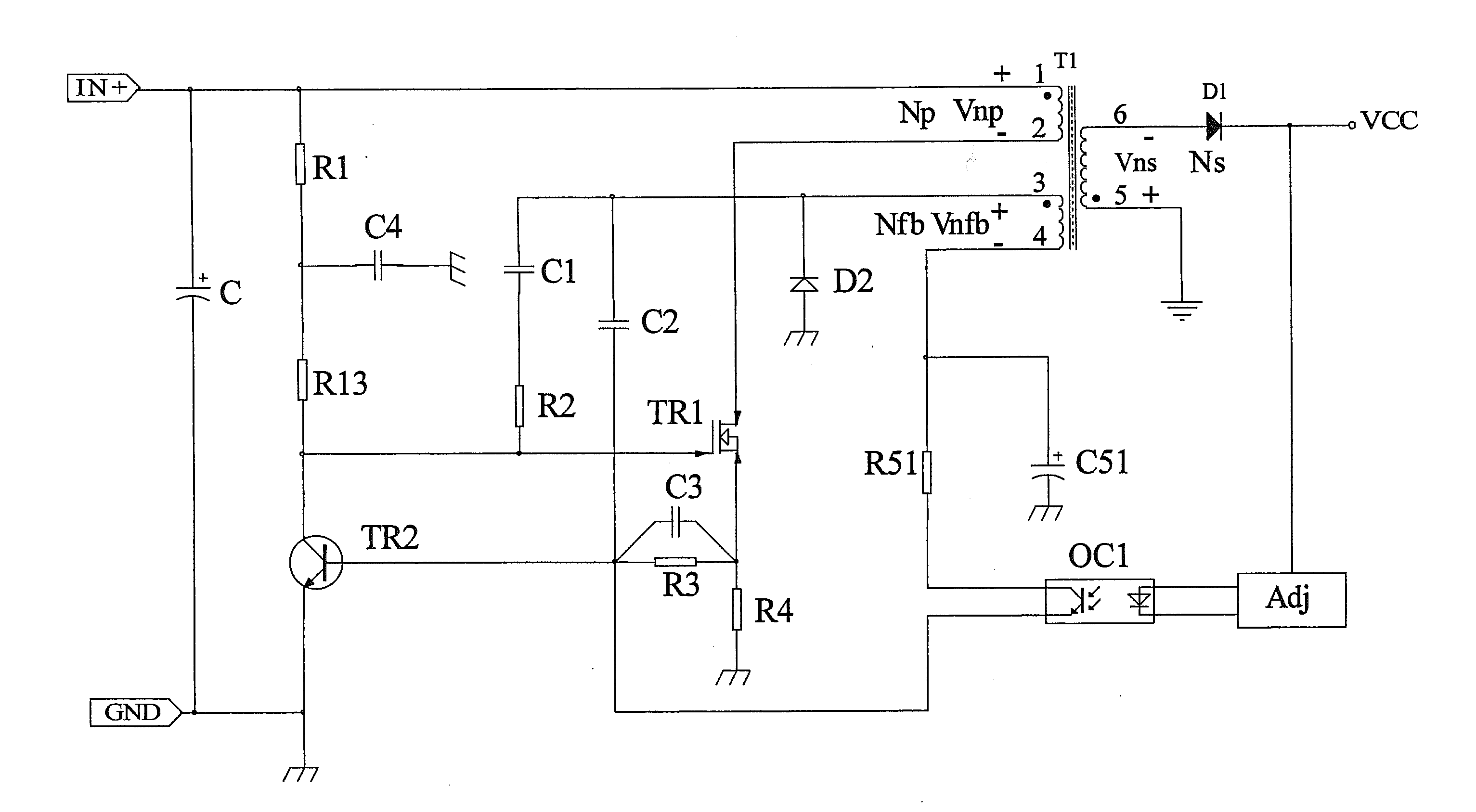
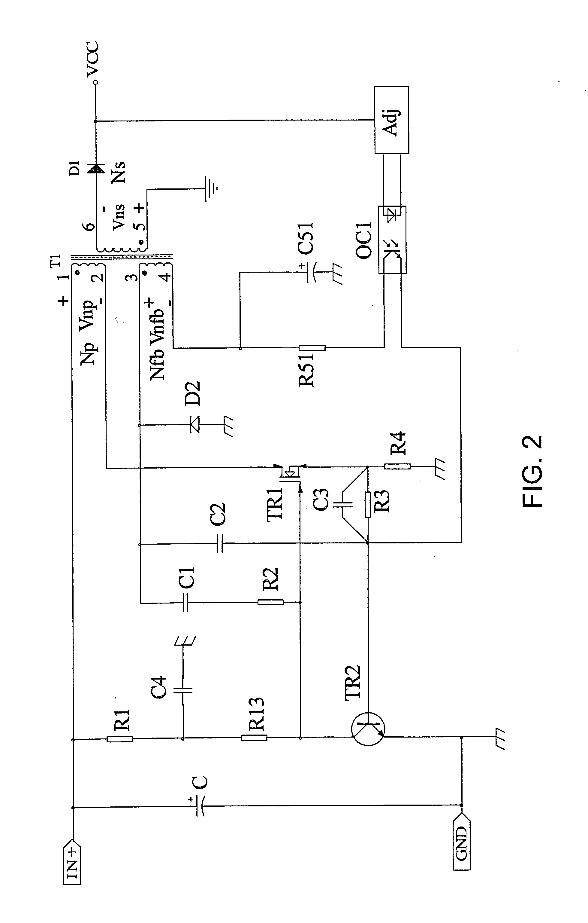
[0017]As shown in FIG. 2, the converter according to the first embodiment of the invention includes a transformer T1, a FET TR1, a photoelectric coupling isolator OC1 and a circuit Adj, the input is connect to the source of the FET TR1 via the primary winding Np of the transformer T1 and to the collector of the transistor TR2 via resistances R1 and R13, the gate of the FET TR1 is connected to the collector of the transistor TR2, and the collector of the transistor TR2 is also connected to the secondary winding Nfb via a resistance R2 and a capacitance C1. The source of the transistor TR1 is connected to ground via a resistance R4 and to the base of the transistor TR2 via parallel connection of a resistance R3 and a capacitance C3. The base of the transistor TR2 is connected to the emitter of the photoelectric coupling isolator OC1, and to the common polarity terminal of the feedback winding Nfb via a capacitance C2. The photoelectric isolator OC1 is connected to the load through the...


PUM


Abstract

An isolating self-oscillation flyback converter includes a coupling transformer T1, a FET TR1, a transistor TR2, a photoelectric coupling isolator OC1 and a load feedback circuit Adj. The common polarity terminal of a feedback winding Nfb of the coupling transformer T1 is connected to the gate of the FET TR1 via a capacitance C1 and a resistance R2, and connected to the base of the transistor TR2 via a capacitance C2. The base of the transistor TR2 is also connected to the emitter of the photoelectric coupling isolator OC1. The photoelectric coupling isolator OC1 is connected to the positive terminal of the output voltage. The opposite polarity terminal of the feedback winding Nfb is connected to the collector of the photoelectric coupling isolator OC1 via a resistance R5, and connected to ground via a capacitance C5. The common polarity terminal of the feedback winding Nfb is also connected to the cathode of a diode D, and the anode of the diode D is connected to ground. A set of windings are removed by forming a loop circuit directly between the feedback winding Nfb and the photoelectric coupling isolator OC1.

Description

1. FIELD OF THE INVENTION [0001]The invention relates to an isolating self-oscillation flyback converter for simplifying the winding structure of a transformer used in the self-oscillation flyback power supply module.2. DESCRIPTION OF THE RELATED ART [0002]Traditional isolating self-oscillation flyback converter includes a transformer, a FET, a transistor, a photoelectric coupling isolator and a circuit Adj, as indicated in FIG. 1, wherein, the input is connected to the source of the FET TR1 via the primary winding P1 of a transformer T and to the collector of a transistor TR2 via resistances R1 and R2, the gate of a FET TR1 is connected to the collector of the transistor TR2, the common polarity terminal of the secondary winding P2 of the transformer T is connected to the collector of the transistor TR2 and the gate of the FET TR1 via a resistance R2 and a capacitance C1 and to the base of the transistor TR2 via a capacitance C2, and the other end of the secondary winding P2 is con...

Claims


Application Information

Patent Timeline
IPC IPC(8): H02M3/335
CPCH02M3/3385
Inventor HUANG, JIANGJIANSONG, JIANFENG
Owner MORNSUN GUANGZHOU SCI & TECH
Why Eureka
Try Eureka