Slave device, time synchronization method in slave device, master device, and electronic equipment system

Active Publication Date: 2010-09-02
SONY CORP
View PDF0 Cites 50 Cited by
  • Summary
  • Abstract
  • Description
  • Claims
  • Application Information

AI Technical Summary

Benefits of technology

[0046]Moreover, in the above embodiment of the present invention, the second value is calculated. The second value is the result of an addition of the transmission delay components (Delay) between the master device and the slave device at the fifth time and an estimate of the time at which the fifth message issued at the fifth time is received by the master device. When the estimate is smaller than an actual receipt time (the sixth time), the frequency of the clocks for counting up the counter of the clock unit is increased. On the other hand, when the estimate is larger than the actual receipt time (the sixth time), the frequency of the clocks is decreased. In this way, a change in the counter values on the counter of the clock unit of the slave device can be matched to an ideal change in the counter values conforming to a

Problems solved by technology

Therefore, it cannot be said that the time on the slave device and the time on the master device are not perfectly

Method used


Image

  • Slave device, time synchronization method in slave device, master device, and electronic equipment system
  • Slave device, time synchronization method in slave device, master device, and electronic equipment system
  • Slave device, time synchronization method in slave device, master device, and electronic equipment system

Examples


Example

[0062]3. Third Embodiment; and

[0063]4. Modified Embodiment

Example

[0064]1. First Embodiment

Exemplary Configuration of Electronic Equipment System

[0065]FIG. 1 illustrates an exemplary configuration of an electronic equipment system 100 according to the first embodiment. The electronic equipment system 100 includes a master device 110 and a slave device 120. For example, when the electronic equipment system 100 is a camera system including a plurality of video cameras, the master device 110 is a video camera serving as a parent device, and the slave device 120 is a video camera serving as a child device. Furthermore, when the electronic equipment system 100 is a control system including a controlling device (computer) and a plurality of controlled devices, the master device 110 is the controlling device, and the slave device 120 is the controlled device.

[0066]For the simplicity's sake, only one slave device 120 is illustrated in FIG. 1. In addition, only those portions related to time synchronization are illustrated in FIG. 1 as the configuration of...

Example

2. Second Embodiment

Exemplary Configuration of Electronic Equipment System

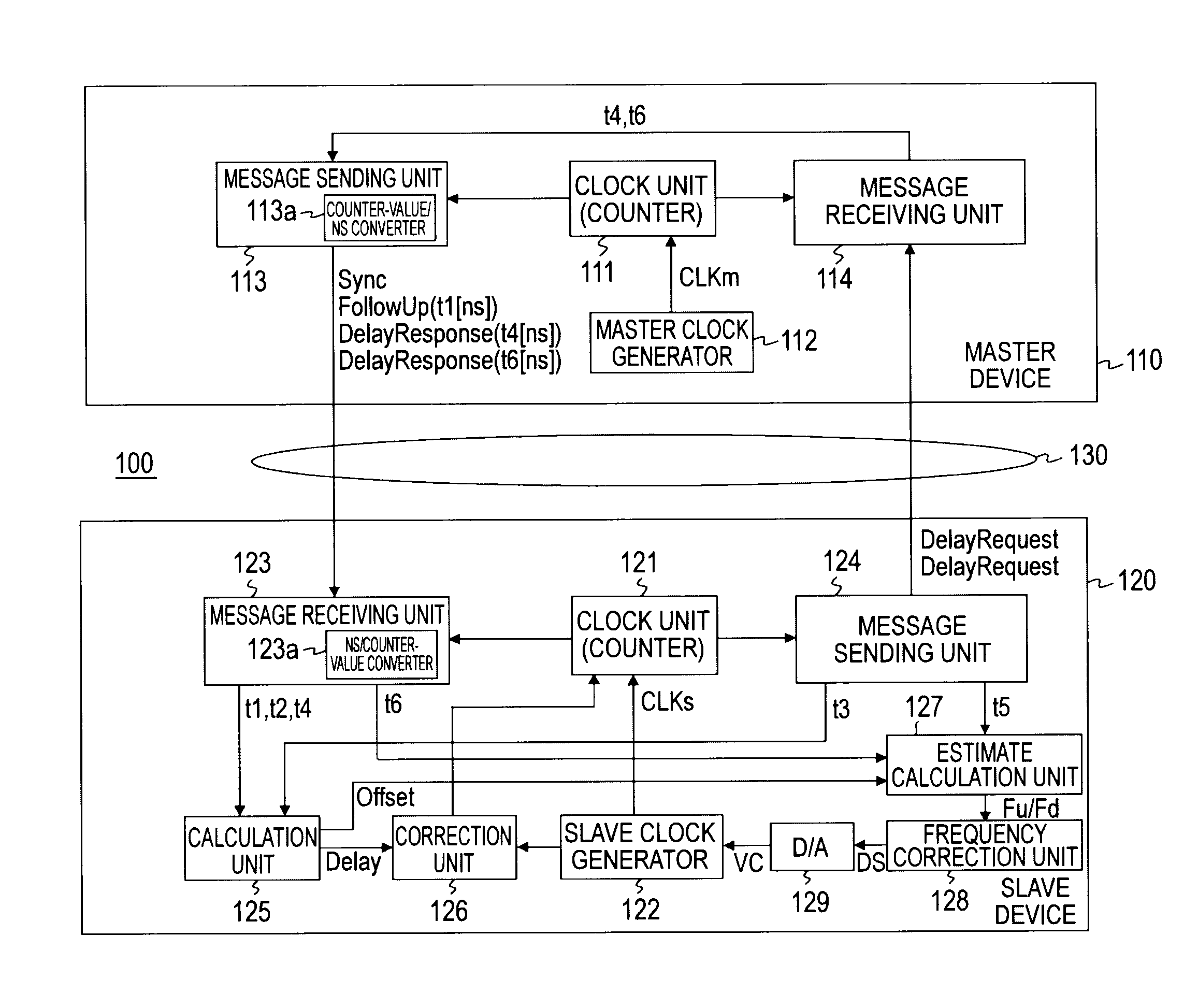
[0117]FIG. 4 illustrates an exemplary configuration of an electronic equipment system 100A according to the second embodiment. The electronic equipment system 100A includes a master device 110A and a slave device 120B similarly to the electronic equipment system 100 illustrated in FIG. 1. In FIG. 4, portions corresponding to those in FIG. 1 will be denoted by the same reference numerals, and description thereof will be omitted.

[0118]The master device 110A includes a clock unit 111, a master clock generator 112, a message sending unit 113A, and a message receiving unit 114.

[0119]The message sending unit 113A sends a PTP (Precision Time Protocol) message to the slave device 120 via a transmission line 130. The PTP message that the message sending unit 113A sends to the slave device 120 includes a Message message in addition to the above-described Sync message, FollowUp message, and DelayResponse message.

[0120]Th...


PUM


Abstract

A slave device includes: a clock unit that is configured by a counter so as to output time information; a clock generation unit that generates clocks for counting up the counter; a message receiving unit that receives messages sent from a master device; a message sending unit that sends messages to the master device; a first calculation unit that calculates a first value necessary for correcting the time on the clock unit; a first correction unit that corrects the time on the clock unit based on the first value calculated by the first calculation unit; a second calculation unit that calculates a second value necessary for correcting a frequency of the clocks generated by the clock generation unit; and a second correction unit that corrects the frequency of the clocks generated by the clock generation unit based on the second value calculated by the second calculation unit.

Description

BACKGROUND OF THE INVENTION[0001]1. Field of the Invention[0002]The present invention relates to a slave device, a time synchronization method in the slave device, a master device, and an electronic equipment system. More particularly, the present invention relates to slave devices enabling realization of perfect time synchronization with a master device.[0003]2. Description of the Related Art[0004]In recent years, more and more media are digitalized, and many devices recording video streams in digital forms are commercialized as represented by video cameras. Moreover, with the digitalization of video streams, an environment has become widespread in which video streams can be edited easily.[0005]An editing operation will be considered in which video streams captured with a plurality of video cameras are combined into a single video stream. This operation uses a method that correlates the video streams with the capturing times with reference to the timestamps of the video streams to ...

Claims


Application Information

Patent Timeline
IPC IPC(8): H04J3/06G04C9/04G04G3/00G04G3/02G04G5/00G04G5/04
CPCG04G5/00G04G7/00H04N21/4302H04N21/242G06F1/12
Inventor INOMATA, NAOKI
Owner SONY CORP
Why Eureka
Try Eureka