

Gas jet nozzle
- Summary
- Abstract
- Description
- Claims
- Application Information
AI Technical Summary
Benefits of technology
Problems solved by technology
Method used
Image

Examples
first embodiment
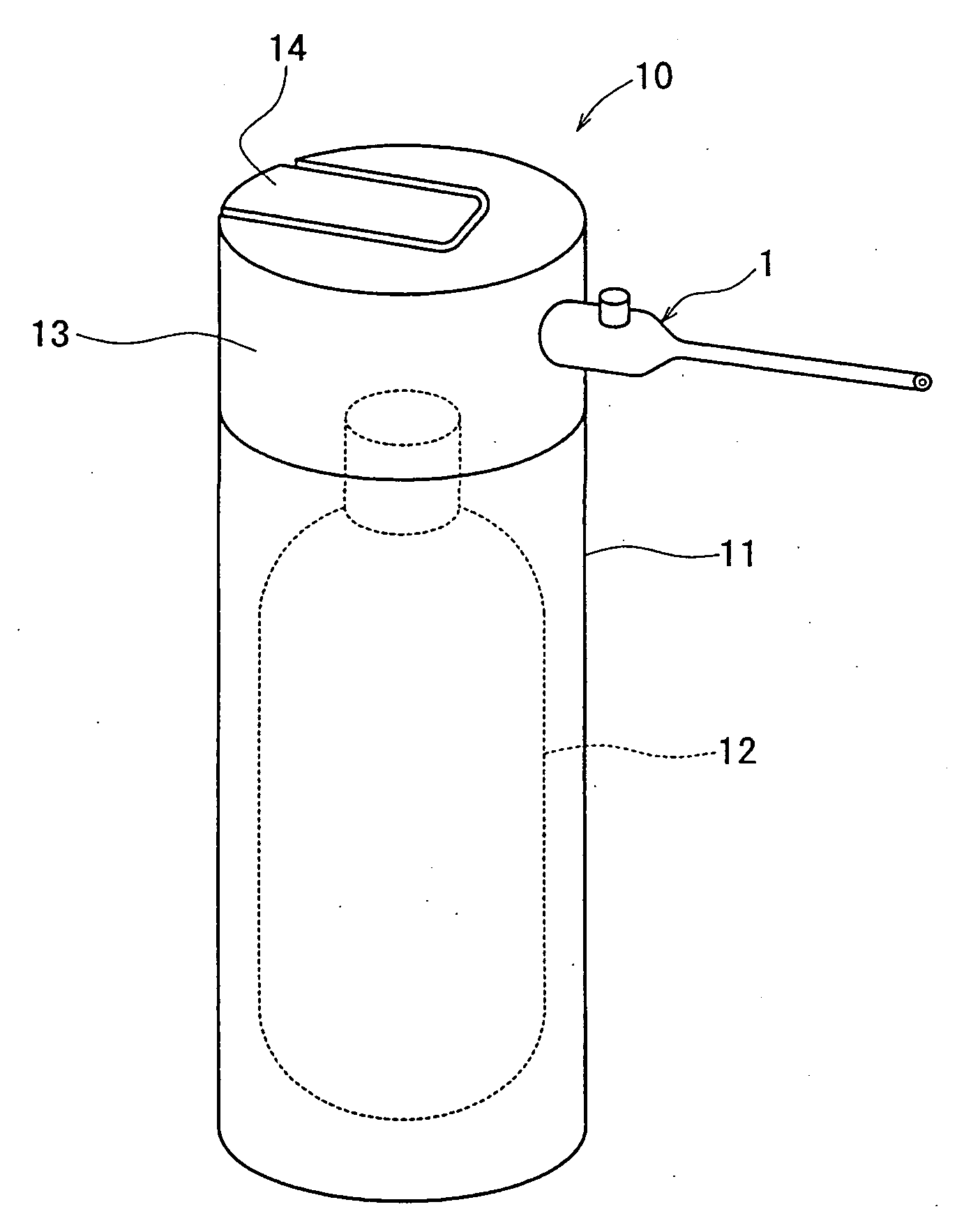
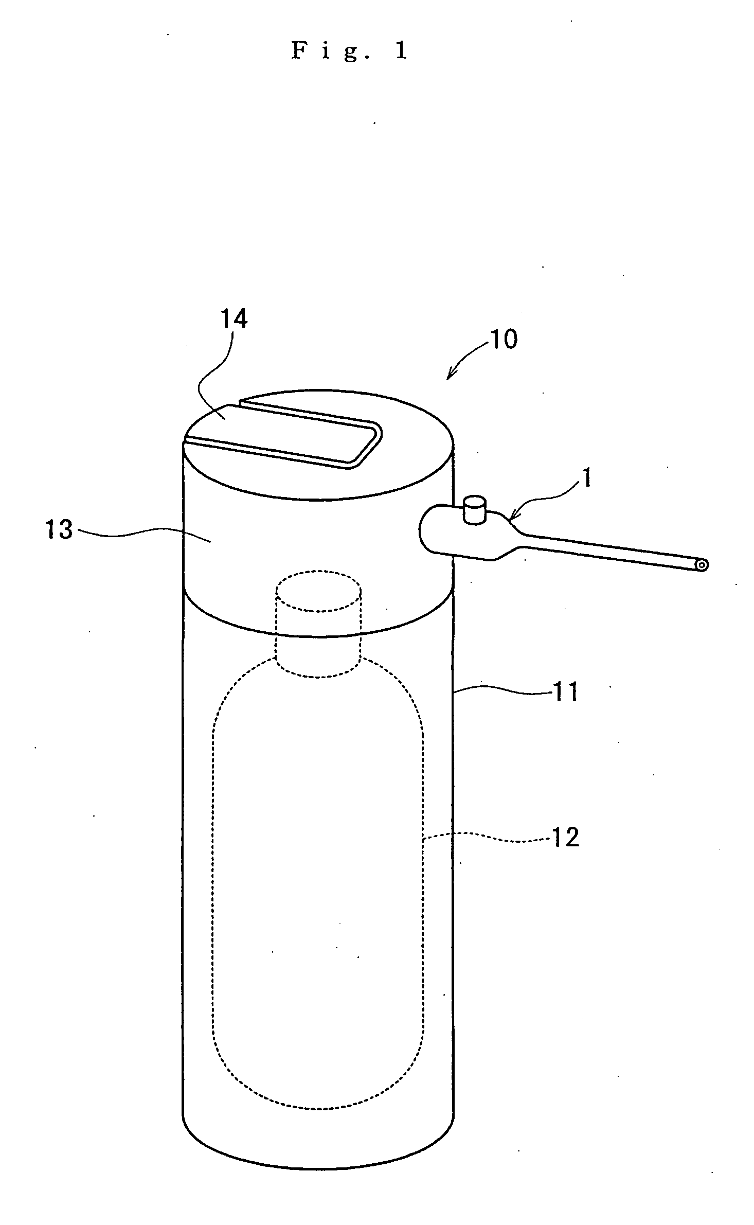
[0024]FIG. 1 shows a dust blower 10 including a gas jet nozzle 1 according to the present invention. The blower 10 further includes a cylindrical casing 11, a high-pressure gas bottle 12 as a high-pressure gas reservoir, a cylindrical gas ejector 13, and a jet button 14.
[0025]The gas bottle 12 is put in the casing 11. The gas ejector 13 is fitted to the top of the casing 11 and includes a valve mechanism (not shown) for jetting out the high-pressure gas in the bottle 12. The jet button 14 is fitted to the top of the ejector 13 and can be pressed to open the valve mechanism. The nozzle 1 is fitted to the cylindrical wall of the ejector 13, which ejects high-pressure gas from the bottle 12 through the gas jet nozzle 1.
[0026]It is preferable that the critical temperature of the high-pressure gas filled into the high-pressure bottle 12 be 30-430 degrees K. The bottle 12 can be filled with gas either compressed under high pressure or liquefied. It is preferable that the liquefied gas sho...
second embodiment
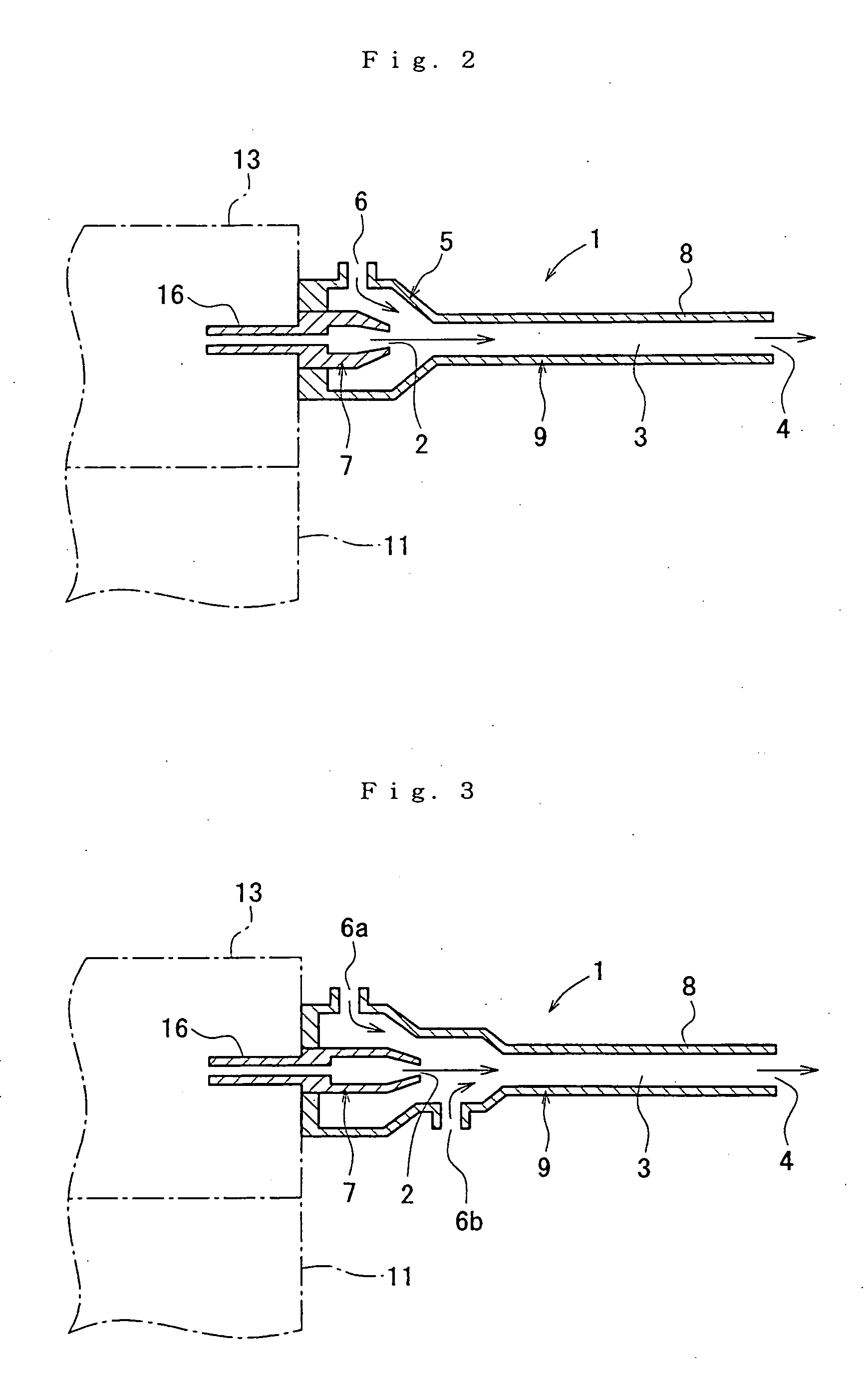
[0036]FIG. 3 shows a gas jet nozzle 1 according to the present invention. The air suction part 5 of this nozzle 1 has a rear air intake port 6a and a front air intake port 6b formed through its peripheral wall. The intake ports 6a and 6b are backward and forward respectively of the jet port 2 and opposite to each other radially of the nozzle.
[0037]The suction part 5 might have two or more rear air intake ports 6a and two or more front air intake ports 6b that are backward and forward respectively of the jet port 2. These intake ports 6a and 6b might alternate around the axis of the suction part 5.
[0038]Otherwise, this embodiment is similar in structure to the first embodiment. The parts of this embodiment that are similar to the counterparts in the first embodiment are assigned the same reference numerals as the counterparts are assigned.
[0039]The gas jetted from the jet port 2 is mixed with the air sucked into the rear air intake port 6a, which is backward of the jet port 2. When t...
third embodiment
[0042]FIG. 4 shows a gas jet nozzle 1 according to the present invention. The air suction part 5 of this nozzle 1 has air intake ports 6 formed through its peripheral wall. The intake ports 6 are spaced at regular intervals around the axis of the suction part 5, along which the first nozzle 7 jets high-pressure gas.
[0043]Otherwise, this embodiment is similar to the first embodiment. The parts of this embodiment that are similar to the counterparts in the first embodiment are assigned the same reference numerals as the counterparts are assigned.
[0044]These intake ports 6 are arranged around the axis of the air suction part 5, along which the first nozzle 7 jets high-pressure gas. The gas jet nozzle 1 sucks atmospheric air through the intake ports 6. The gas jetted from the first nozzle 7 is mixed with the sucked air. The mixed gas is jetted out at a higher flow rate than by the first and second embodiments. This makes it possible to further reduce consumption of high-pressure gas, wi...
PUM
 Abstract
Description
Claims
Application Information