

Ammonia removal equipment, ammonia removal method, and hydrogen gas production method
- Summary
- Abstract
- Description
- Claims
- Application Information
AI Technical Summary
Benefits of technology
Problems solved by technology
Method used
Image

Examples
first embodiment
[0047]Hereinafter, the ammonia removal equipment and the ammonia removal method according to the present embodiment will be described with reference to accompanying drawings.
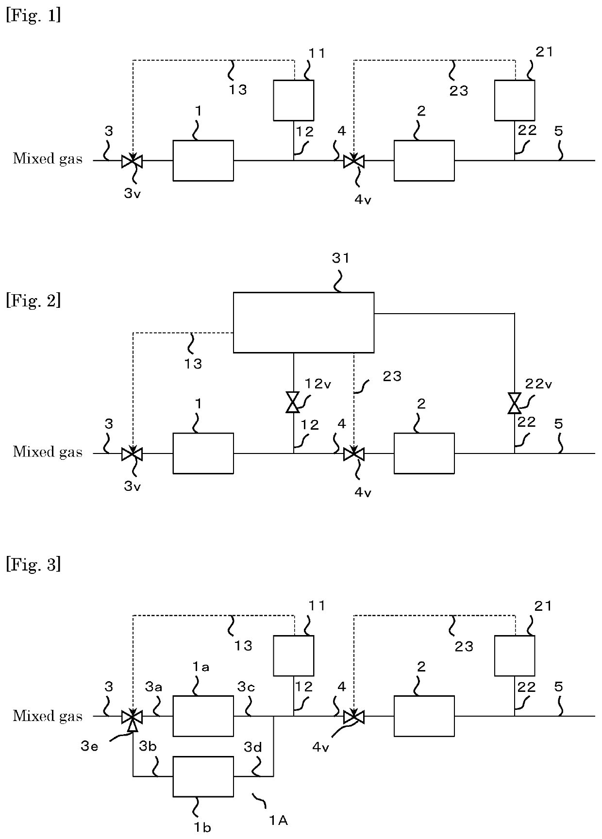
[0048]FIG. 1 shows a schematic diagram illustrating the ammonia removal equipment according to the first embodiment.
[0049]The ammonia removal equipment according to the first embodiment comprises: a first ammonia removal apparatus 1; a second ammonia removal apparatus 2 that is installed at a stage subsequent to the first ammonia removal apparatus 1 and that treats a first treated gas treated by the first ammonia removal apparatus 1; a first ammonia concentration measurement apparatus 11 that measures an ammonia concentration in the first treated gas treated by the first ammonia removal apparatus 1; and a second ammonia concentration measurement apparatus 21 that measures an ammonia concentration in a second treated gas treated by the second ammonia removal apparatus 2.
[0050]A pipe 3 provided with an opening / clo...
second embodiment
[0116]FIG. 2 shows a schematic diagram illustrating the ammonia removal equipment according to the second embodiment.
[0117]The ammonia removal equipment according to the second embodiment comprises: a first ammonia removal apparatus 1; a second ammonia removal apparatus 2 that is installed at a stage subsequent to the first ammonia removal apparatus 1 and that treats a first treated gas treated by the first ammonia removal apparatus 1; and a first ammonia concentration measurement apparatus 31 that is capable of measuring an ammonia concentration in the first treated gas treated by the first ammonia removal apparatus 1 and an ammonia concentration in the second treated gas treated by the second ammonia removal apparatus 2.
[0118]A pipe 3 provided with an opening / closing valve 3v is connected to an inflow port of the first ammonia removal apparatus 1. An outflow port of the first ammonia removal apparatus 1 and an inflow port of the second ammonia removal apparatus 2 are connected by ...
third embodiment
[0133]FIG. 3 shows a schematic diagram illustrating the ammonia removal equipment according to the third embodiment.
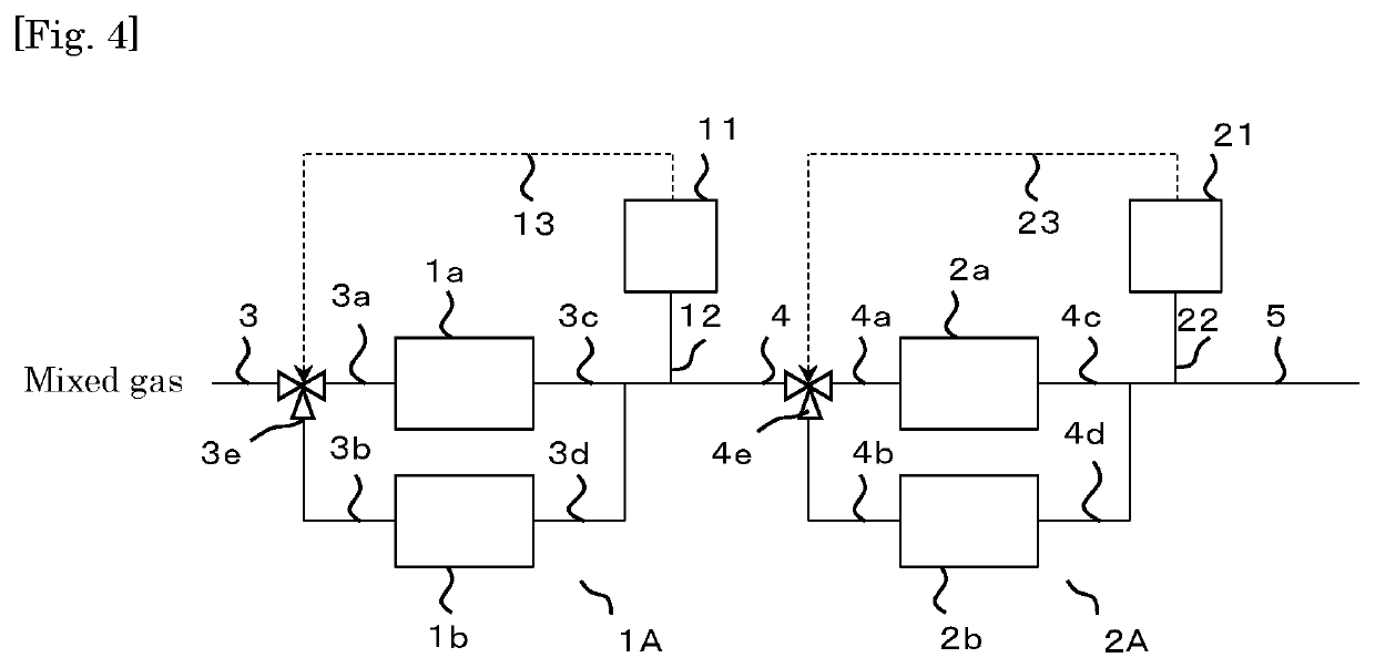
[0134]The ammonia removal equipment is the same as the ammonia removal equipment according to the first embodiment except that a first ammonia removal apparatus 1A comprising a plurality of (two in the present embodiment) first ammonia removal containers 1a, 1b installed in parallel and a three-way valve 3e are used in place of the first ammonia removal apparatus 1 and the opening / closing valve 3v in the ammonia removal equipment according to the first embodiment.
[0135]In addition, the reference signs that are the same as those in the ammonia removal equipment according to the first embodiment denote the same parts as those in the ammonia removal equipment according to the first embodiment.
[0136]Specifically, the first ammonia removal apparatus 1A comprises: two first ammonia removal containers 1a, 1b installed in parallel; two pipes 3a, 3b into which the pipe 3 branch...
PUM
| Property | Measurement | Unit |
|---|---|---|
| Concentration | aaaaa | aaaaa |
Abstract
Description
Claims
Application Information