Elastic Image Display Method and Elastic Image Display Device

an image display and elastic technology, applied in the field of elastic image display methods and elastic image display devices, can solve the problems of lowering test efficiency, requiring extra burden on patients, and difficulty in accurately distinguishing benignancies and malignancies, so as to improve the accuracy of differentiating benignancies and improve the effect of visibility without losing real-time efficiency

Active Publication Date: 2010-09-02
HITACHI LTD
View PDF4 Cites 30 Cited by
  • Summary
  • Abstract
  • Description
  • Claims
  • Application Information

AI Technical Summary

Benefits of technology

[0020]In accordance with the present invention, it is possible to improve accuracy in differentiating benignancy and malignancy of biological tissues in the gray zone of an elastic image, and to provide an elastic image display method and elastic image display device with superior visibility without losing real-time efficiency.BRIEF DESCRIPTION OF THE DIAGRAMS
[0021]FIG. 1 shows a configuration diagram of an ultrasonic diagnostic apparatus in embodiment 1 for executing the elastic image display method of the present invention.
[0022]FIG. 2 shows a configuration of a two-dimensional color map for constructing a color elastic image of embodiment 1 related to the present invention.
[0023]FIG. 3 shows an example of the relationship between elasticity modulus among the respective regions of mammary gland tissues.
[0024]FIG. 4 shows a two-dimensional color map and a color elastic image in practical

Problems solved by technology

However, for example, elasticity of cancer cells, depending on the region or individual variability, is often approximated to the elasticity of normal biological tissues (for example, fiber tissues), and is often difficult to accurately distinguish benignancy and malignancy even by observing the elastic image which is color mapped in accordance with the elasticity.
However, when conclusive evidence can not be obtained by one elastic image, since the same target region needs to be observed for evaluation by switching to the other elastic images, the operation becomes complicated and time consuming whereby lowering the test efficiency, and requires extra burdens to a patient.

Method used


Image

  • Elastic Image Display Method and Elastic Image Display Device
  • Elastic Image Display Method and Elastic Image Display Device
  • Elastic Image Display Method and Elastic Image Display Device

Examples


embodiment 1

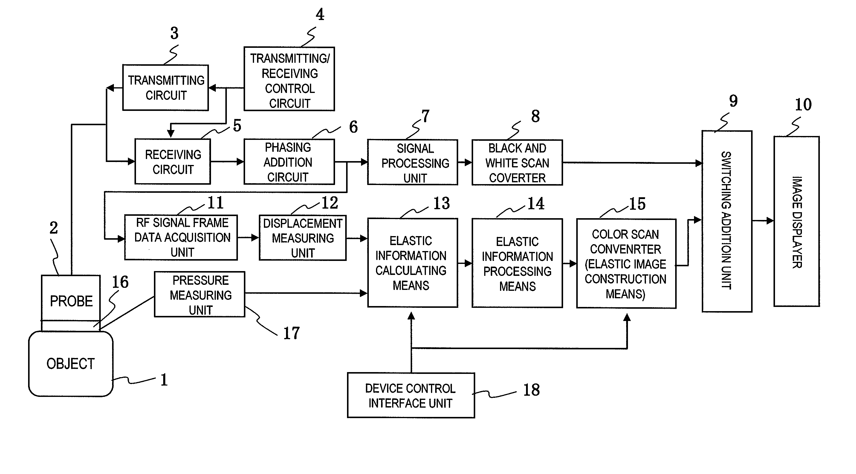
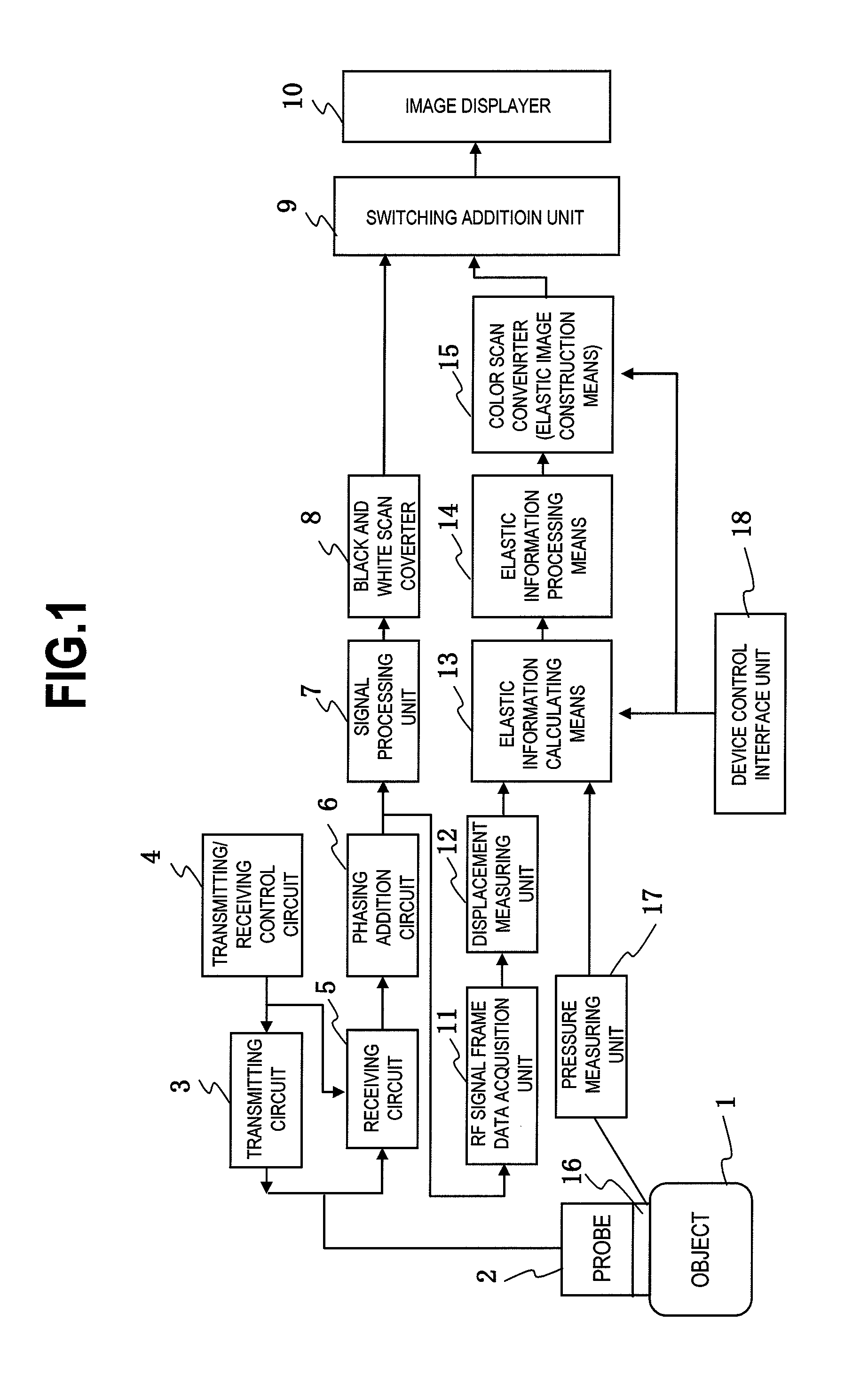
[0034]As an example of the elastic image display device of the present invention, for example, a block configuration diagram of a first embodiment of an ultrasonic diagnostic apparatus will be shown in FIG. 1. As shown in the diagram, an ultrasonic probe 2 for applying to an object 1 is formed having ultrasonic transmission / reception plane in which a plurality of transducers for transmitting / receiving ultrasonic waves to / from the object 1 are arranged. The probe 2 is driven by ultrasonic pulses supplied from a transmission circuit 3. A transmission / reception control circuit 4 controls the timing for transmitting an ultrasonic pulse for driving a plurality of transducers of the probe 2, and forms an ultrasonic beam toward the focal point set in the object 1. Also, the transmission / reception control circuit 4 electronically scans an ultrasonic beam in arrangement direction of the transducers of the probe 2.

[0035]On the other hand, the probe 2 receives the reflected echo signals genera...

example 1

Practical Example 1

[0059]As the relevant elastic information of the present invention, embodiment 1 to which the non-linear parameter for representing the nonlinearity of elastic modulus with respect to the strain amount is applied will be described. A relevant elastic information calculating unit by which the elastic information calculating unit 13 of the present embodiment is configured obtains non-linear parameter α which represents the nonlinearity as the elastic feature of the biological tissues in the target region, as shown in the 2-dimensional color map in FIG. 4 (A).

[0060]More specifically, as shown in FIG. 5, while the biological tissues generally have the characteristic that they harden more as the pressure or strain amount of compression increases and fatty tissues exhibit linearity wherein the approximately constant elasticity modulus is measured up to the range of large strain amount, fiber tissues and invasive tumors show the phenomenon of strain hardening due to dras...

example 2

Practical Example 2

[0070]FIG. 6 (A) shows a 2-dimensional color map of embodiment to which S / N determination information related to the reliability of calculation result as relevant elastic information other than elasticity modulus E is applied, and FIG. 6 (B) shows an example of the color elastic image wherein the images are synthesized based on the two items of elastic information that are the elastic modulus and S / N determination information.

[0071]A relevant elastic information calculating unit of an elastic information calculating unit 13 in the present embodiment comprises an S / N determination information calculating unit. The S / N determination information calculating unit is for acquiring S / N determination information represented by local dispersion (variance) of displacement distribution included in the calculation result of the displacement or coefficient of correlation obtained by displacement calculation of the displacement measuring unit 12.

[0072]The displacement frame da...


PUM


Abstract

[Problems] The accuracy in distinguishing between malignant and benign tissues in a gray zone of an elastic image is improved.[Means for Solving Problems] According to a 2-dimensional map having longitudinal and horizontal axes indicating different elastic information, hue or luminance of each pixel is mapped correspondingly to their elastic information, and the elastic information is combined to construct one elastic image.With this, a plurality of items of elastic information can be combined into one elastic image and displayed, and thereby the elastic image can be scanned in real time while observing it.Even where one item of elastic information may be in a gray zone, i.e., benign or malignant, another item of information may definitely show the differentiation between benign or malignant, and therefore highly accurate differentiation is possible.In addition, the user can perform diagnosis with the elastic image into which the plurality of items of elastic information is combined without moving the line of sight, thereby obtaining an improved visibility.

Description

TECHNICAL FIELD[0001]The present invention relates to an elastic image display method and elastic image display device, more particularly to the elastic image display method and elastic image display device effective in observing an elastic image indicating elastic information of biological tissues and perform diagnosis of benignancy or malignancy of the diseased area.BACKGROUND ART[0002]The diseased area such as a tumor of biological tissues is diagnosed, since the tissues are harder than the other normal tissues, by constructing an elastic image of the cross-section of a living body including the target region based on the elastic information wherein the elasticity of the biological tissues are measured by an ultrasonic diagnostic apparatus or magnetic resonance imaging apparatus. The relevant prior art is disclosed in Patent Documents 1 and 2.[0003]As for an elastic image, for example, for an ultrasonic diagnostic apparatus, an image such as a displacement distribution image cons...

Claims


Application Information

Patent Timeline
Patent Type & Authority Applications(United States)
IPC IPC(8): G06K9/62
CPCA61B8/08A61B8/461G01S7/52042G01S7/52071G01S7/52074A61B8/485A61B8/463
Inventor MATSUMURA, TAKESHI
Owner HITACHI LTD
Why Eureka
Try Eureka