Cartridge and electrophotographic image forming apparatus

a technology of electrophotographic image and forming apparatus, which is applied in the direction of electrographic process apparatus, instruments, optics, etc., can solve the problems of increasing man-hour, increasing difficulty in assembling, and limited material selection

Active Publication Date: 2010-09-02
CANON KK
View PDF7 Cites 35 Cited by
  • Summary
  • Abstract
  • Description
  • Claims
  • Application Information

AI Technical Summary

Benefits of technology

[0011]Accordingly, it is an object of the present invention to provide a cartridge and an electrophotographic image forming apparatus wherein the movement of the rotational-driving-force-transmitting member r

Problems solved by technology

However, in order to raise insertion pressure, the increase of a dimensional accuracy of the through-hole is required, and the material which does not break easily must be used, and therefore, the material selection is limited.
In the case o

Method used


Image

  • Cartridge and electrophotographic image forming apparatus
  • Cartridge and electrophotographic image forming apparatus
  • Cartridge and electrophotographic image forming apparatus

Examples


first embodiment

General Arrangement

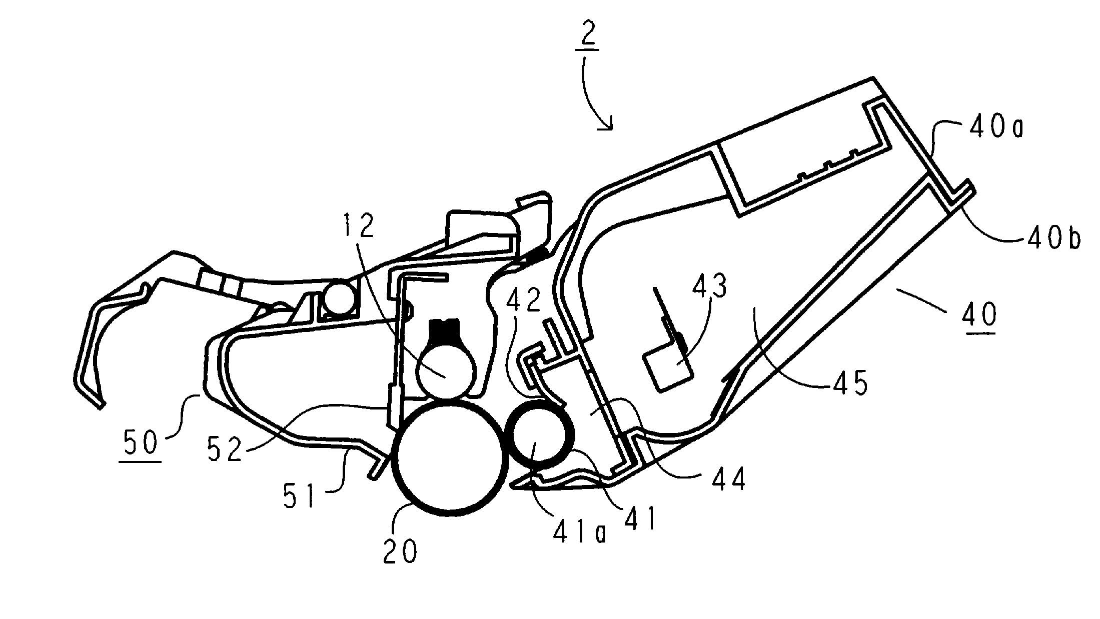
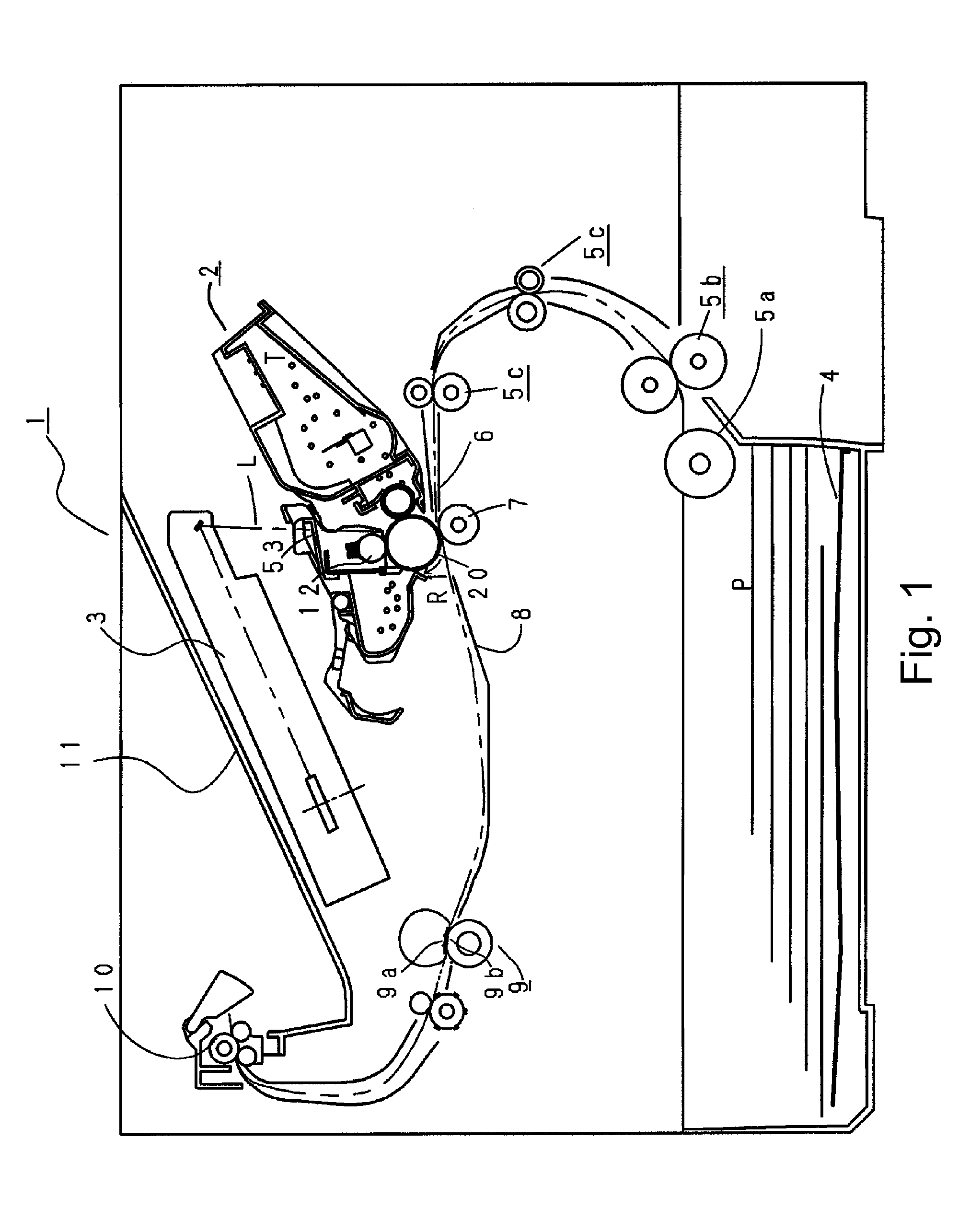
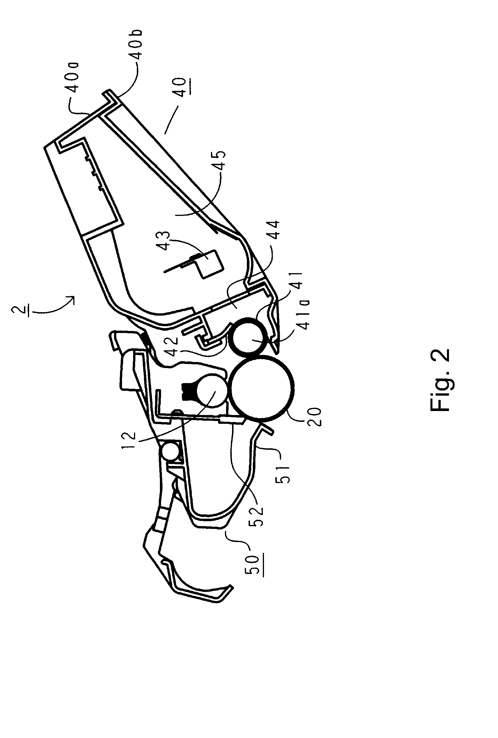
[0068]FIG. 1 is a sectional view of a main assembly 1 and a process cartridge 2 of an electrophotographic image forming apparatus according to the embodiment. FIG. 2 is a sectional view of the process cartridge 2 according to the embodiment. Referring to FIGS. 1 and 2, the general arrangement of the image forming apparatus and an image forming process will be described.

[0069]In this image forming apparatus, the process cartridge (cartridge) 2 is detachably mountable to the main assembly 1 of the electrophotographic image forming apparatus. It is a laser printer of an electrophotographic type. When the cartridge 2 is mounted to the main assembly 1, the upper portion of the cartridge 2 is provided with an exposure device (laser scanner unit) 3. The lower portion of the cartridge 2 is provided with a sheet tray 4 for containing a recording material (sheet material) P. Furthermore, the main assembly 1 is provided with a pick-up roller 5a, a feeding roller 5b, a feedin...

second embodiment

[0189]Referring to FIG. 44-FIG. 46 the description will be made as to a device according to the second embodiment. The basic structures of the device of this embodiment is the same as that of the embodiment described above, and therefore the redundant description is omitted for the sake of simplicity. The like reference numerals as in the foregoing embodiments are assigned to the elements having the corresponding functions.

[0190]These embodiments are different in the structure of the coupling assembly 156 from the first embodiment. In the coupling assembly 156 of this embodiment, the coupling 150 and the spherical member 160 are connected directly to each other using a connecting portion 150t provided in the coupling 150 and the connecting portion 160c provided for the spherical member 160.

[0191]Part (a) FIG. 44 is a perspective view illustrating the coupling assembly of this embodiment, and (b) FIG. 44 is a sectional view illustrating the connection of the coupling 150 and the sphe...

third embodiment

[0203]Referring to FIG. 47-FIG. 50 the description will be made as to the device according to the third embodiment. The basic structures of the device of this embodiment are the same as that of the first embodiment, and therefore, the redundant description is omitted. The like reference numerals as in the foregoing embodiments are assigned to the elements having the corresponding functions.

[0204]Part (a) of FIG. 47 is a perspective view illustrating the coupling assembly, and part (b) of FIG. 47 is a sectional view illustrating the coupling assembly.

[0205]These embodiments are different in the structures of the coupling assembly 156 and the flange 151 from the first embodiment. As shown in (a) and (b) of FIG. 47, the coupling 150 of this embodiment comprises the substantially spherical portion 150R which is provided with the through-hole 150r. The pin 155 is inserted into the through-hole 150r, and is fixed by the insertion pressure or the like between the through-hole 150r and the ...


PUM


Abstract

A cartridge mountable and dismountable by moving in the direction crossing with an axial direction of the drive shaft of a main assembly of the apparatus, includes a rotatable member rotatable by receiving a rotational force from the apparatus; a coupling engageable with the rotational force applying portion to receive a force for rotating said rotatable member, said coupling including a coupling member rotatable about an axis, a first rotational force receiving portion, provided at one end portion of said coupling member, for receiving the rotational force from the driving shaft, a rotational force transmission member engaged with the other end portion of said coupling member and having opposite ends projected out in a crossing wherein said coupling member is pivotable between a transmitting angular position for transmitting the rotational force from the driving shaft to said rotatable member and a mounting-and-dismounting angular position which is inclined relative to the axis of said rotatable member; a flange mounted to said rotatable member and rotatable about an axis, said flange including an opening accommodating said transmission member with a gap, a regulating portion, provided in said opening, for regulating movement of said transmission member in the crossing direction when said coupling takes the transmitting angular position, a second rotational force receiving portion for being abutted by said transmission member to receive the rotational force from said coupling, an opposing portion opposing to said second receiving portion, wherein in a state that said coupling is in the transmitting angular position and that one end of said transmission member contacts to said regulating portion to be confined in movement, when said coupling inclines relative to said flange such that a side in which a projection distance of said rotational force transmission member is relatively smaller moves away from said first receiving portion, an engagement depth between said side of said transmission member and said second receiving portion and an engagement depth between said side of said transmission member and said opposing portion are larger than zero.

Description

FIELD OF THE INVENTION AND RELATED ART[0001]The present invention relates to a cartridge mountable and dismountable relative to the main assembly by being moved in the direction crossing with an axial direction of a drive shaft of a main assembly of an electrophotographic image forming apparatus, and relates to an electrophotographic image forming apparatus loaded by this.[0002]The electrophotographic image forming apparatuses include an electrophotographic copying machine and an electrophotographic printer (laser beam printer and LED printer or the like).[0003]For example, the cartridge is a process cartridge or a developing cartridge, and it is dismountably mounted to the electrophotographic image forming apparatus main assembly to contribute to an image forming process for forming an image on a recording material.[0004]Here, the process cartridge includes an electrophotographic photosensitive member and the process means which functions on the electrophotographic photosensitive m...

Claims


Application Information

Patent Timeline
IPC IPC(8): G03G15/00
CPCG03G21/1853G03G21/1864G03G21/186
Inventor HARA, NOBUYOSHIMORIOKA, MASANARI
Owner CANON KK
Why Eureka
Try Eureka