

Cable tie
- Summary
- Abstract
- Description
- Claims
- Application Information
AI Technical Summary
Benefits of technology
Problems solved by technology
Method used
Image

Examples
Embodiment Construction
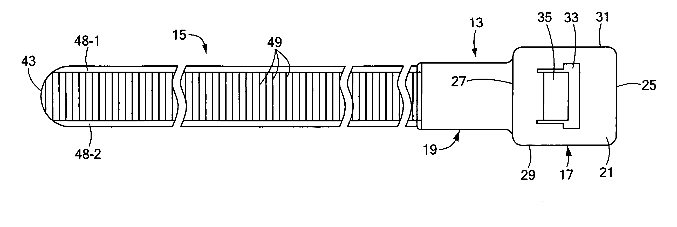
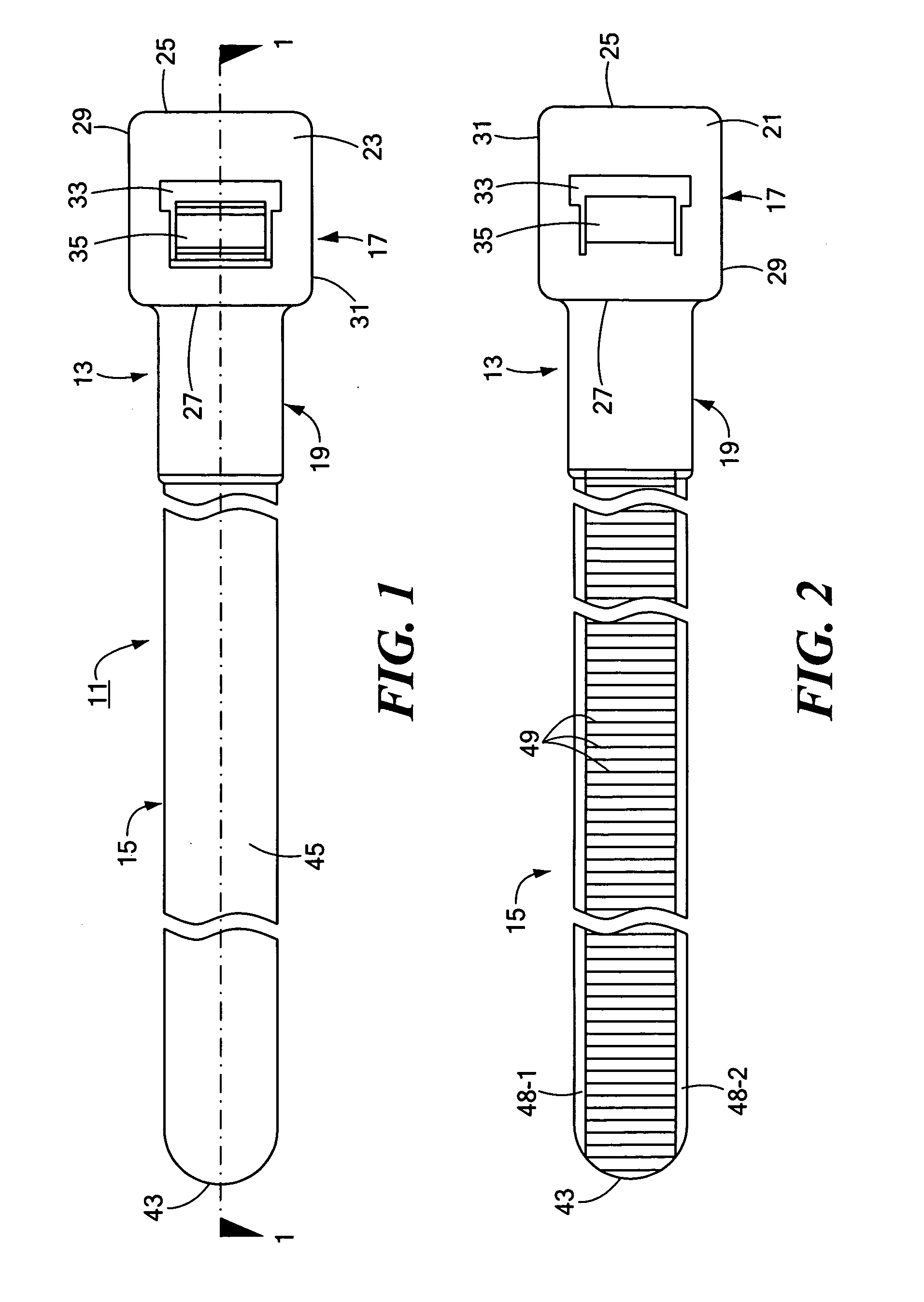
[0060]Referring now to FIGS. 1 and 2, there are shown various views of a cable tie constructed according to the teachings of the present invention, the cable tie being represented generally by reference numeral 11. In use, cable tie 11 can be formed into a locked closed loop in order to bundle together a plurality of objects, such as cables and / or wires.
[0061]The present inventors have determined that the failure of two-piece cable ties of the type described in the '855 patent most commonly occurs as a result of either pawl failure or insert-mold failure rather than strap failure. Accordingly, as will be described in greater detail below, cable tie 11 combines the basic design and method of manufacture of the two-piece cable disclosed in the '855 patent with certain design and manufacturing enhancements that result in an increased load rating, these enhancements serving as the primary novel features of the present invention. More specifically, the enhancements of the present inventi...
PUM
 Abstract
Description
Claims
Application Information