Shipboard Vessel Having a Vertically Aligned Scrubber and Process Component

a scrubber and process technology, applied in the direction of water/sewage treatment by oxidation, liquid degasification, separation processes, etc., can solve the problems of inapplicability of land-based methods to shipboard plants and inappropriate shipboard plants

a scrubber and process technology, applied in the direction of water/sewage treatment by oxidation, liquid degasification, separation processes, etc., can solve the problems of inapplicability of land-based methods to shipboard plants and inappropriate shipboard plants

US20100224070A1Inactive Publication Date: 2010-09-09PATTERSON RONALD G +1

Image

  • Shipboard Vessel Having a Vertically Aligned Scrubber and Process Component
  • Shipboard Vessel Having a Vertically Aligned Scrubber and Process Component
  • Shipboard Vessel Having a Vertically Aligned Scrubber and Process Component

Examples


Embodiment Construction

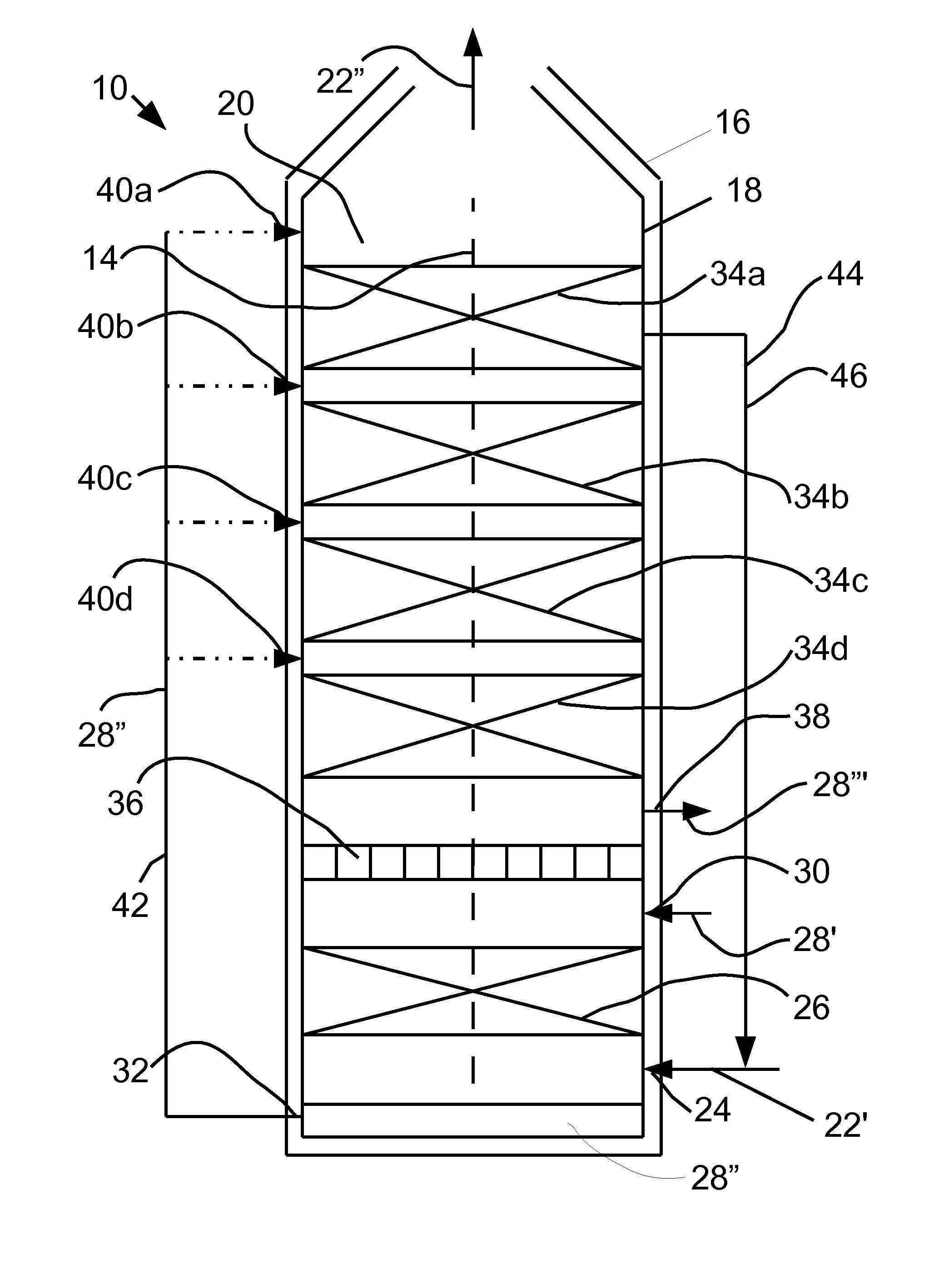
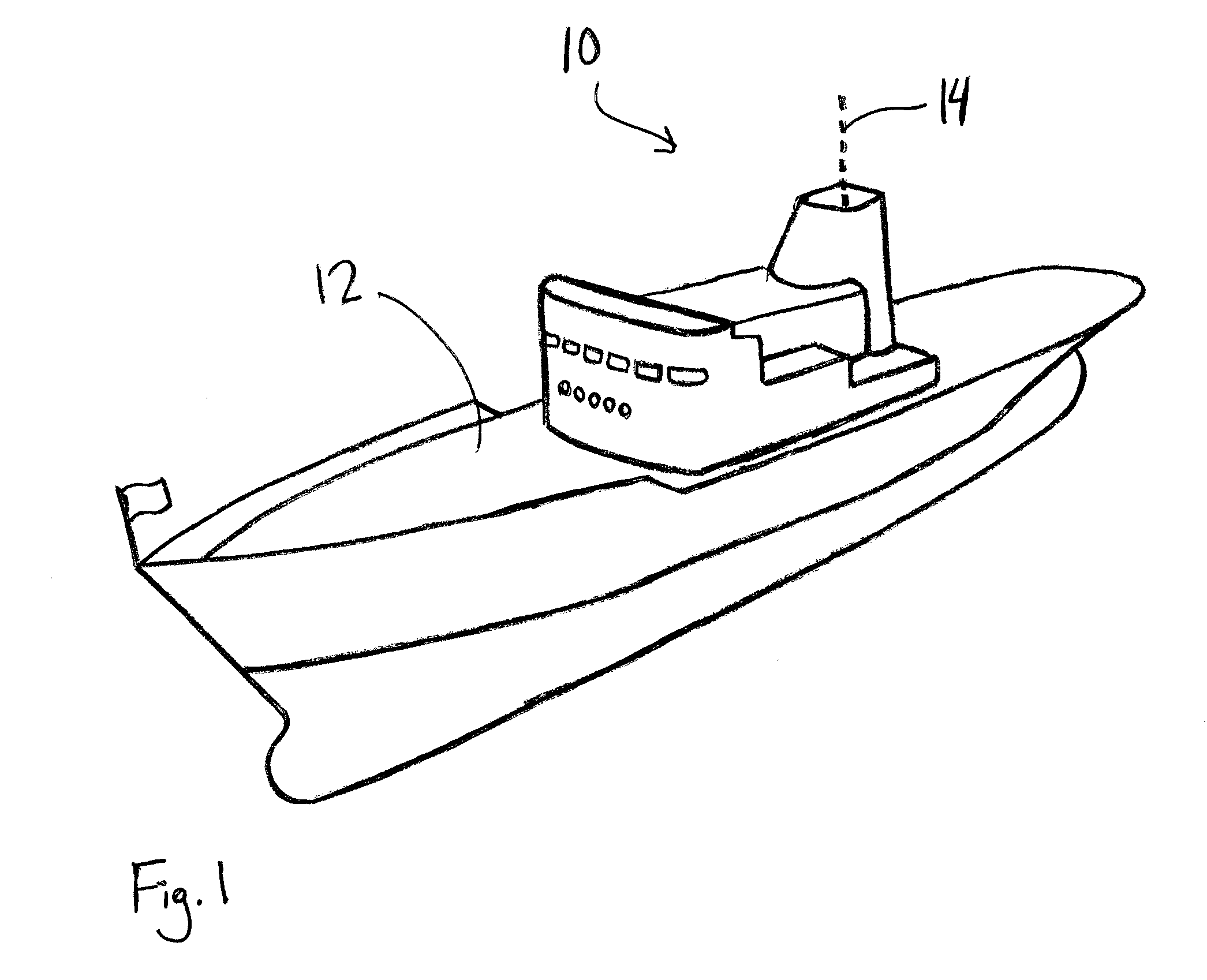
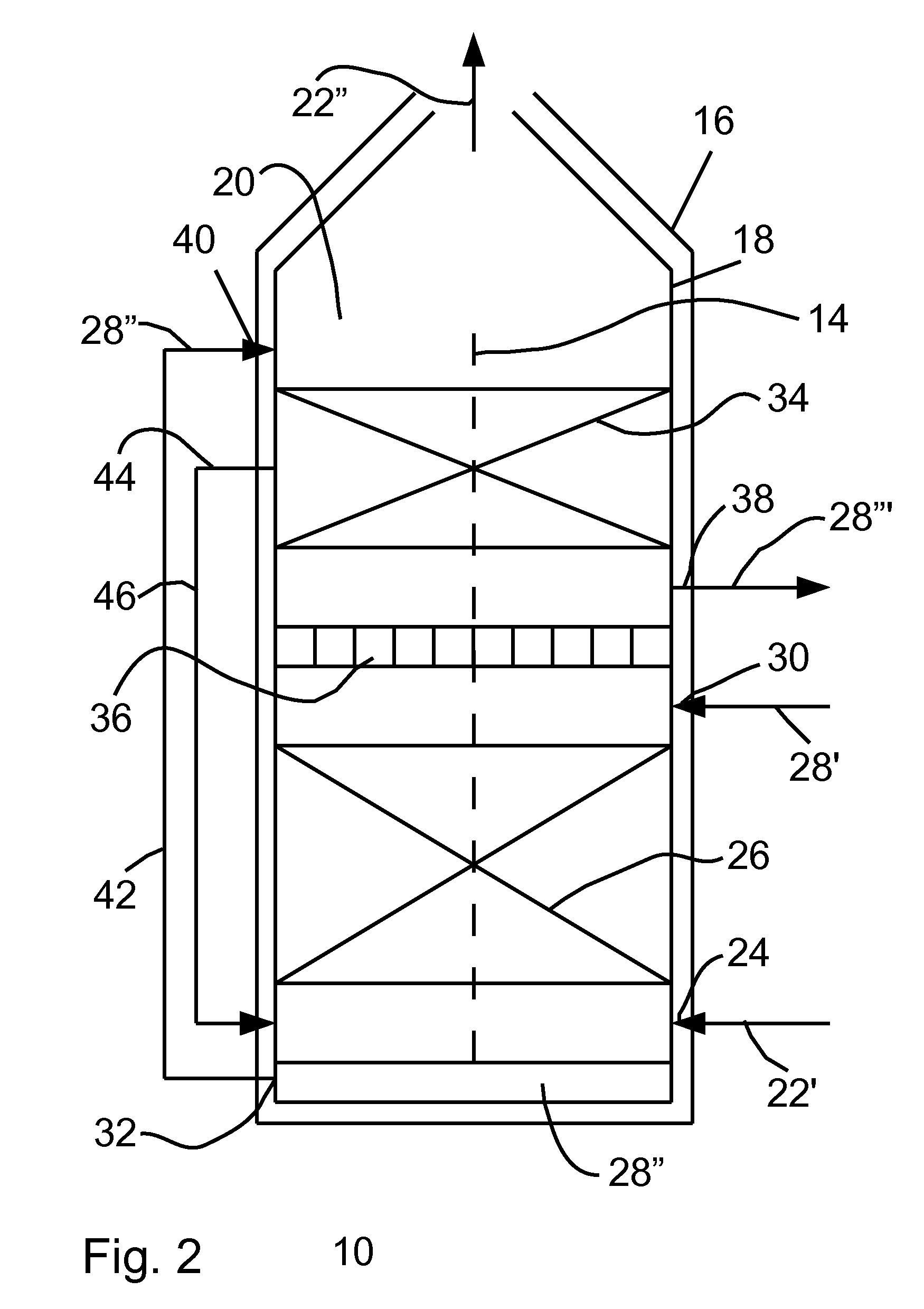
[0019]Referring initially to FIG. 1, a vessel apparatus is shown and generally designated 10. As shown, the vessel apparatus 10 is formed and defined by a ship 12. Further, the shipboard vessel apparatus 10 defines a vertical axis 14. Referring now to FIG. 2, it can be seen that the vessel apparatus 10 includes a vessel 16 having a wall 18 that bounds a chamber 20 which extends along the axis 14.

[0020]As illustrated in FIG. 2, the vessel apparatus 10 is intended to scrub pollutants from exhaust gases 22′ that are produced during the combustion of diesel ship fuel and that have a sulfur content of about 2.9 or 3%. Therefore, the apparatus 10 provides for an exhaust port 24 formed at the bottom end of the vessel 16 to introduce the exhaust gases 22′ into the chamber 20. Also, a scrubber 26 is located within the chamber 20 and may be designed for optimal removal of sulfur dioxide from the exhaust gases 22′ in certain embodiments. For this purpose, the scrubber 26 utilizes seawater 28′ ...


PUM

PropertyMeasurementUnit
Molar densityaaaaaaaaaa
Chemical oxygen demand (mass)aaaaaaaaaa
Alkalinityaaaaaaaaaa

Abstract

The vessel apparatus processes exhaust gases and effluent seawater on a ship. Structurally, the vessel apparatus includes a vertically oriented vessel. Further, a scrubber is positioned within the vessel to remove pollutants from the exhaust gases with seawater. Also, an effluent seawater processing component is positioned in the vessel above the scrubber. Between the processing component and the scrubber is a liquid barrier that prevents effluent seawater from entering the top of the scrubber while allowing exhaust gases to pass from the scrubber to the top of the vessel. For operation of the apparatus, effluent seawater resulting from the scrubbing process is recirculated from below the scrubber to a location in the vessel above the processing component. As a result, the effluent seawater may be processed above the scrubber.

Description

CROSS-REFERENCE TO RELATED APPLICATIONS[0001]The present application is related to the co-pending application entitled “Caustic-Assisted Seawater Scrubber System”, application Ser. No. 12 / 398,947, filed on Mar. 5, 2009 and incorporated herein by reference in its entirety.FIELD OF THE INVENTION[0002]The present invention pertains generally to a vessel for processing fluid streams on a ship to eliminate pollutants. More particularly, the present invention pertains to a vertically oriented vessel formed in a ship that holds a scrubber at a position beneath a component for treating effluent seawater. The present invention is particularly, but not exclusively, useful as a vessel apparatus that includes a first stage seawater scrubber and a second stage effluent seawater processing component, such as a degasifier, an oxidizer, a caustic addition stage, or a separator to provide effluent seawater that is environmentally safe for discharge into the sea.BACKGROUND OF THE INVENTION[0003]As is...

Claims


Application Information

Patent Timeline
09 Sep 2010
Publication
US20100224070A1
IPC
B01D53/18; B01D19/00; B01D53/50; B01D53/14; C02F1/72
CPC
B01D53/1425; B01D53/1456; B01D53/18; B01D53/507; B01D53/78; B01D2251/304; Y02C10/06; B01D2251/404
Inventors
PATTERSON, RONALD G.; OLDS, ANDREW J.