Spindle positioning means of linear actuator

a technology of positioning means and linear actuators, which is applied in the direction of electrical apparatus, dynamo-electric machines, propulsion systems, etc., can solve the problems of high price, high material cost, and inability to easily machine high-strength spindles during the manufacturing process, so as to reduce material cost, reduce manufacturing costs, and overcome machining or assembly errors between spindles and positioning posts.

Active Publication Date: 2010-09-09
TIMOTION TECH CO LTD
View PDF10 Cites 2 Cited by
  • Summary
  • Abstract
  • Description
  • Claims
  • Application Information

AI Technical Summary

Benefits of technology

[0006]The present invention is to provide a spindle positioning means of a linear actuator, whereby the free end of the spindle can be supported by a cylinder firmly. Thus, the breakage of the spindle caused by a lateral action force can be prevented efficiently.
[0008]In comparison with prior art, the present invention has advantageous features as follows. Since the free end of the spindle is supported by the cylinder sufficiently, it is unnecessary to manufacture the spindle with a high-strength steel material, which can reduce the material cost and manufacturing cost greatly. With the size of the periphery of the trough being larger than that of an outer thread, the machining or assembling errors between the spindle and the positioning post can be overcome efficiently, so that the cylinder can support the free end of the spindle sufficiently. With reinforcement ribs being formed between the cylinder and the extension plate, the supporting structure of the cylinder can be reinforced. Further, with the troughs being arranged at identical intervals, the action force of the spindle supported by the cylinder can be distributed uniformly.

Problems solved by technology

Since the worm screw is supported at one side, the worm screw may be broken easily during the transmission between the worm screw and the worm wheels.
In addition to high price, such a high-strength spindle cannot be machined easily during the manufacturing process.
Thus, such a product is high in price, so that it cannot be widely used in the industry.
Most manufacturers utilizes the process shown in FIG. 1 to manufacture the linear actuator, in which a cover b on the worm screw a is provided with a supporting hole c whose diameter is significantly larger than that of the free end of the worm screw a, thereby using the supporting hole c to partially support the free end of the worm screw a. However, such a way of partially supporting the worm screw cannot overcome the problem that the worm screw may be broken due to a lateral action force.

Method used


Image

  • Spindle positioning means of linear actuator
  • Spindle positioning means of linear actuator
  • Spindle positioning means of linear actuator

Examples


Embodiment Construction

[0015]The characteristics and technical contents of the present invention will be explained with reference to the accompanying drawings. However, the drawings are illustrative only but not used to limit the present invention.

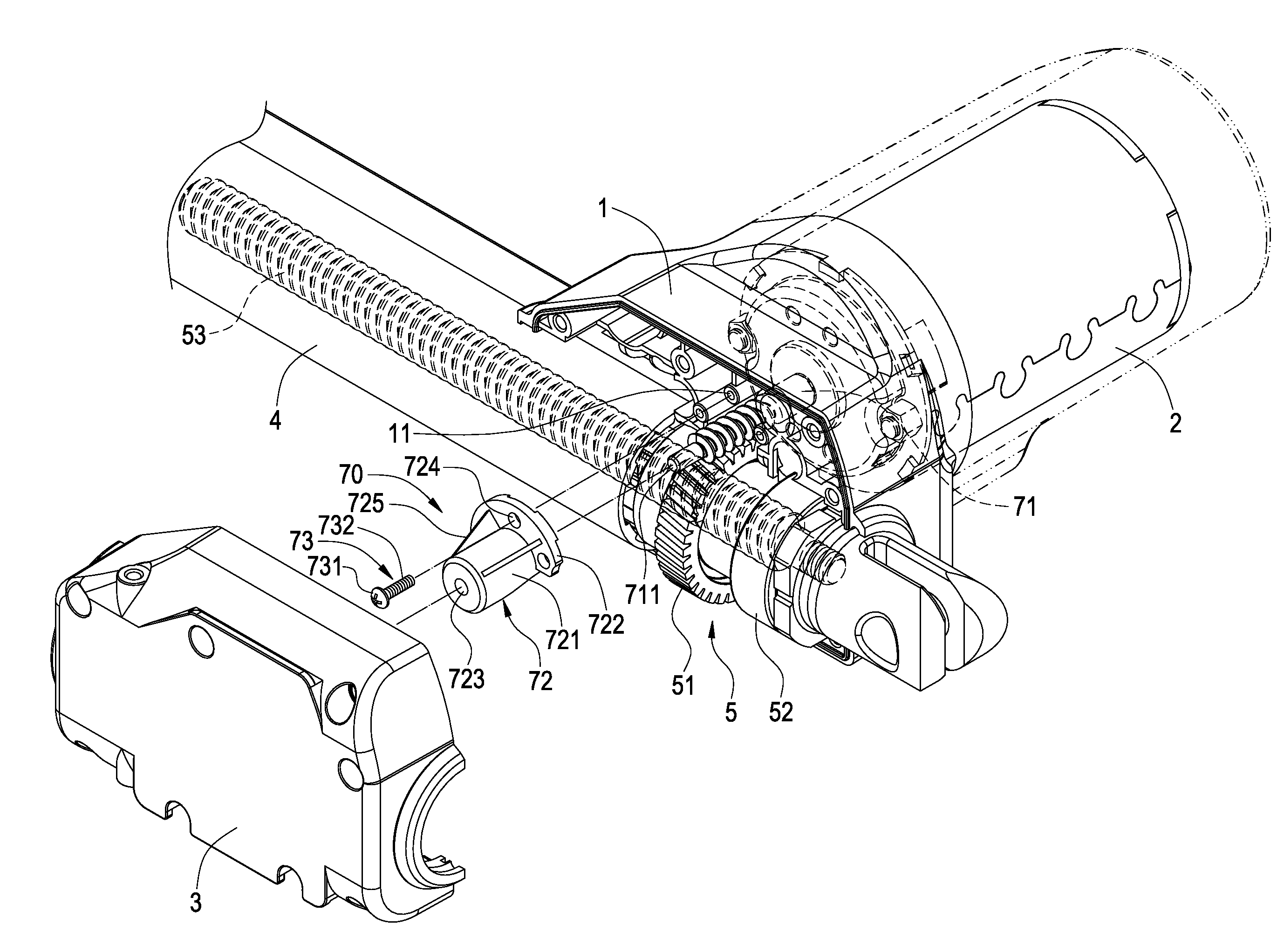
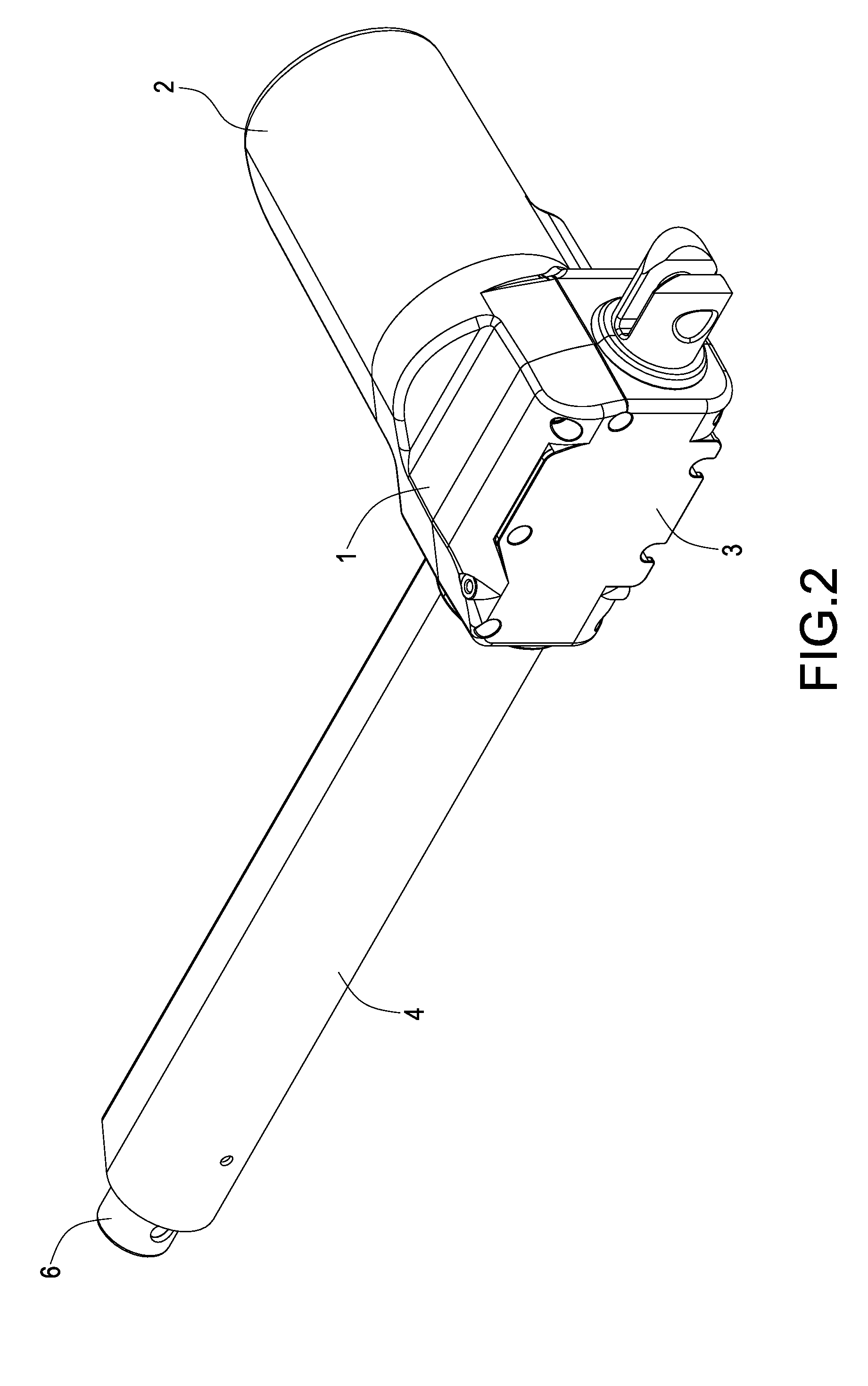
[0016]Please refer to FIGS. 2 and 3. The present invention provides a spindle positioning means of a linear actuator. The linear actuator includes a base 1, an electric motor 2, a cover 3, an outer pipe 4, a transmission means 5 and a telescopic rod 6. The base 1 is substantially formed into an elongate rectangular frame with three positioning posts 11 protruding therein. The positioning posts 11 can be formed into a uniform shape. The electric motor 2 is fixed below the base 1. The cover 3 covers on the base 1. The outer pipe 4 is fixed to the base 1 via the cover 1 and is perpendicular to the electric motor 2. The space between the cover 3 and the base 1 is provided with the transmission means 6 including a worm wheel 51, a bearing 52 and a lead screw 53. The ...


PUM


Abstract

A linear actuator includes a base having a positioning post and a motor fixed on one side of the base. A spindle positioning means includes a spindle, a seat and a fixing element. The spindle protrudes from the motor and penetrates the base. One side of the spindle away from the motor is formed with a free end. The seat includes a cylinder and an extension plate protruding outwards from the periphery of the cylinder. The extension plate is provided with a trough. The cylinder is connected to the free end of the spindle. The trough of the extension plate is located to correspond to the positioning post. The fixing element passes through the trough to fix the seat on the positioning post. Via this arrangement, the breakage of the spindle caused by a lateral force can be prevented efficiently.

Description

BACKGROUND OF THE INVENTION[0001]1. Field of the Invention[0002]The present invention relates to a spindle positioning means, and in particular to a spindle positioning means of a linear actuator.[0003]2. Description of Prior Art[0004]Linear actuator is used to drive a lead screw to rotate via a motor and a driving assembly including a worm screw and worm wheels. The lead screw drives a connected telescopic pipe to extend or retreat linearly. Thus, the linear actuator is widely applied to many apparatuses such as a hospital bed, electric chair or other fields in which an extending or retreating action is needed. Usually, the worm screw in a common linear actuator extends from the spindle center of the motor directly or is connected to the spindle center of the motor via a coupler. One end of the worm screw (i.e. the spindle center of the motor) away from the motor is formed with a free end naturally. During the transmission between the worm screw and the worm wheels, the worm screw ...

Claims


Application Information

Patent Timeline
IPC IPC(8): H02K7/116
CPCH02K7/1166
Inventor TSENG, KUAN-SHU
Owner TIMOTION TECH CO LTD
Why Eureka
Try Eureka