
Rotational Angle Detector And Rotational Angle Detector Incorporated Bearing Assembly

Inactive Publication Date: 2010-09-09
NTN CORP
View PDF2 Cites 12 Cited by
  • Summary
  • Abstract
  • Description
  • Claims
  • Application Information

AI Technical Summary

Benefits of technology

[0008]An object of the present invention is to provide a rotational angle detecting device capable of securing an accurate information on the angle of rotation at the time without any time lag and a detector incorporated bearing assembly having the rotational angle detecting device incorporated therein and also to provide a rotational angle detecting device that can be used to detect the angle of rotation of a rotary shaft of, for example, a motor to accurate detect the angle of rotation at an arbitrarily chosen time and a detector incorporated bearing assembly having this rotational angle detecting device incorporated therein.

Problems solved by technology

For this reason, when the rotational speed of the rotating member is high, a deviation occurs between the actual rotational speed and the rotational angle detected and, therefore, there has been a problem that difficulty is encountered in using in the field of use where precise information on the position of rotation is required in real time.
Because of this, a problem has been recognized that the angle data outputted has a time lag corresponding to the length of time required to perform the angle calculation and no accurate information on the angle at the time of observation can be obtained.
Also, where the rotation of the motor is to be performed by detecting the angle of rotation and the rotational speed with the use of this rotational angle detecting device, difficulty has been encountered in accurately detecting the angle of rotation and the rotational speed at an arbitrarily chosen time.

Method used


Image

  • Rotational Angle Detector And Rotational Angle Detector Incorporated Bearing Assembly
  • Rotational Angle Detector And Rotational Angle Detector Incorporated Bearing Assembly
  • Rotational Angle Detector And Rotational Angle Detector Incorporated Bearing Assembly

Examples


first embodiment

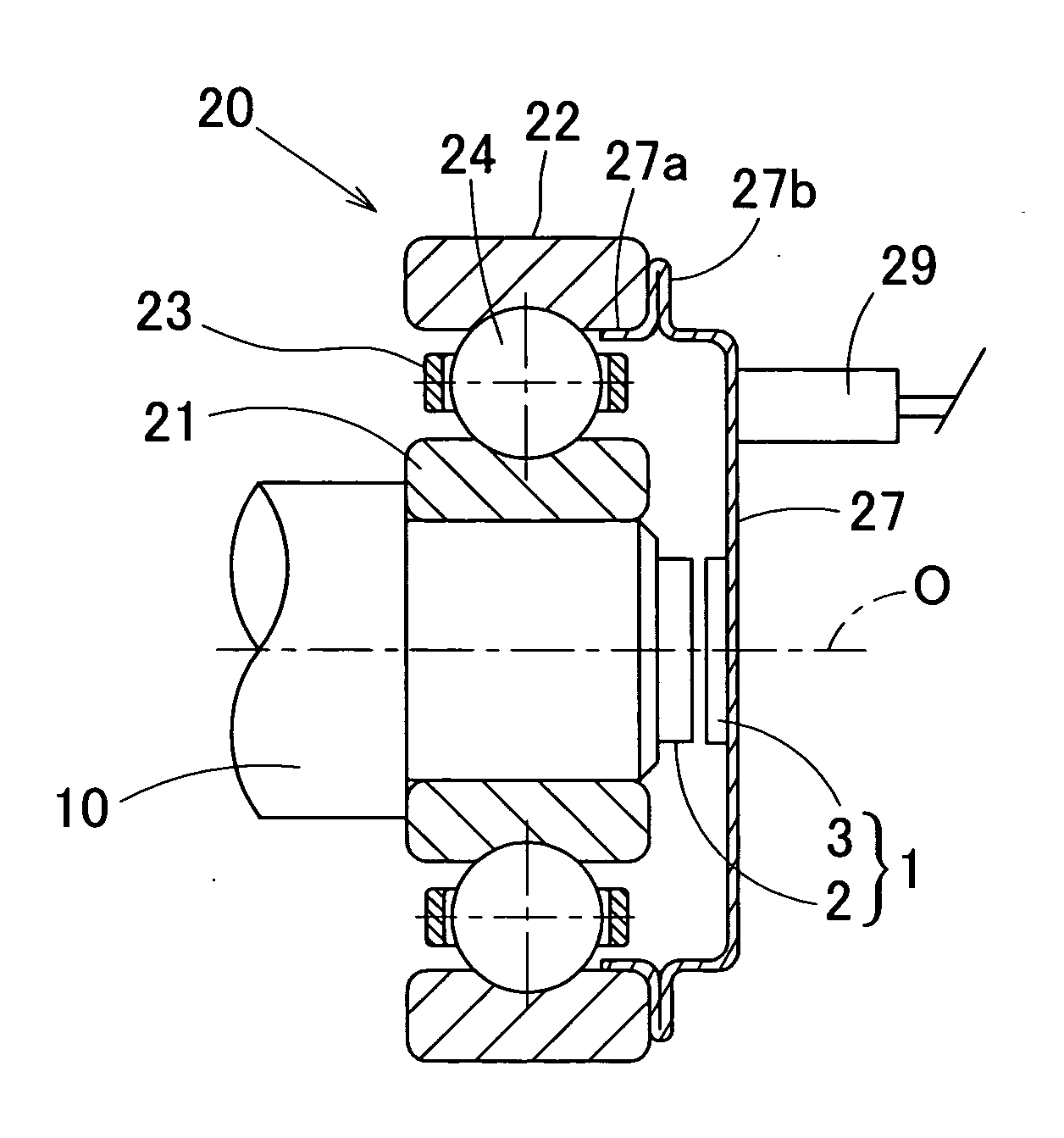
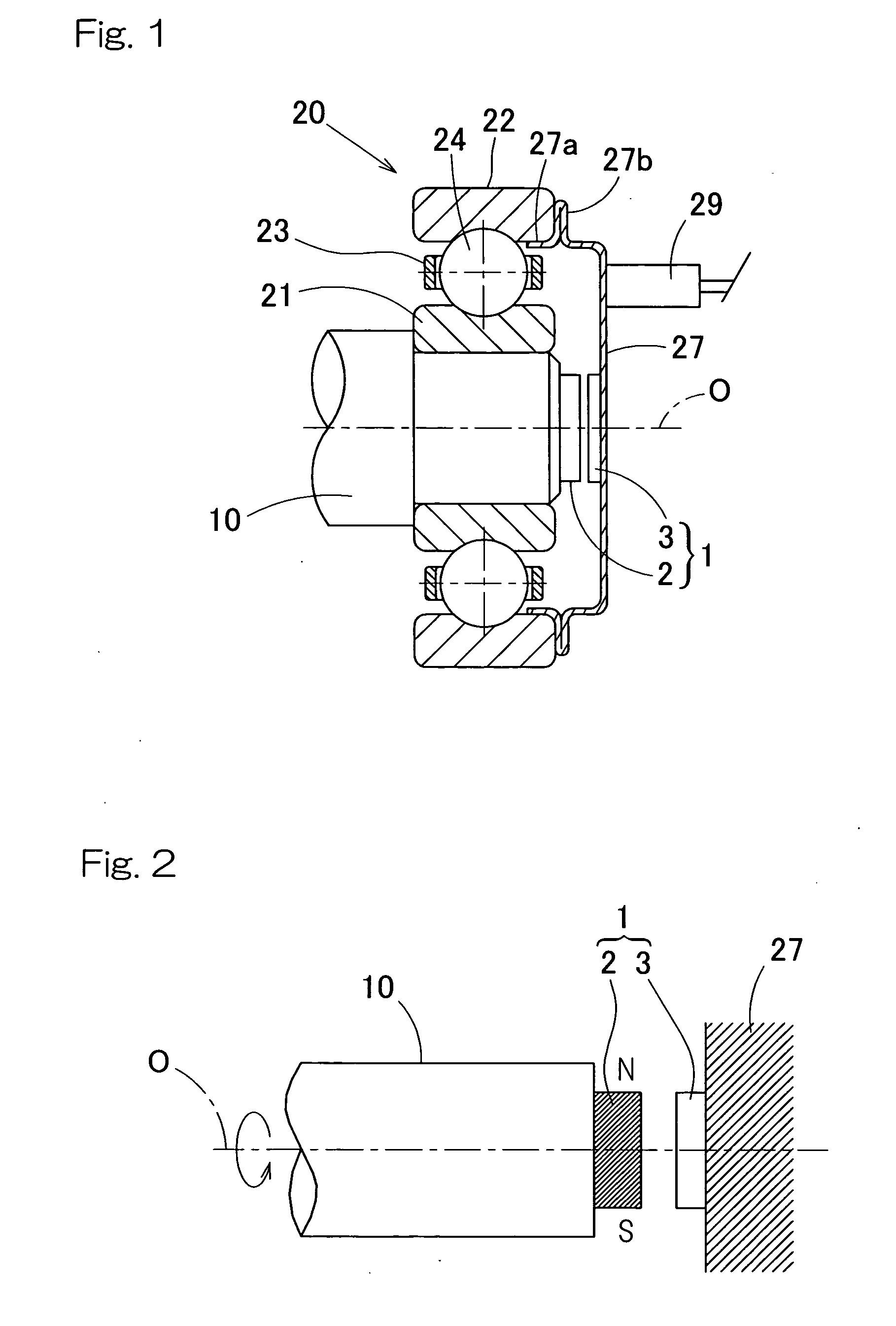
[0047]A first preferred embodiment of the present invention will be described with particular reference to FIGS. 1 to 9. FIG. 1 illustrates a sectional view of a bearing assembly, in which a rotation detecting device is incorporated. This detecting device incorporated bearing assembly 20 is in the form of a rolling bearing assembly, in which rolling elements 24 retained by a retainer 23 are interposed between an inner race 21 and an outer race 22. The rolling elements 24 are in the form of balls and this rolling bearing assembly 20 is rendered to be a single row deep groove ball bearing. The inner race 21 has a rotary shaft 10, which is a rotating member, press-fitted thereinto, and the outer race 22 is arranged in a housing (not shown) of a machine utilizing the bearing assembly.

[0048]The rotation detecting device 1 incorporated in the rolling bearing assembly 20 includes a magnet 2 arranged on the side of the inner race 21 of the rolling bearing assembly 20, and a rotation sensor...

second embodiment

[0070]FIG. 11 illustrates a second preferred embodiment of the present invention. The rotation detecting device according to this second embodiment is similar to that shown in and described in connection with the previous embodiment with reference to FIG. 6, but differs therefrom in that a function ON / Off unit 19 is additionally employed for selectively switching on or off the function of each of the delay time correcting unit 7 and the interpolation unit 8. The function ON / OFF unit 19 includes an automatic switching section 30 and an automatic switching speed setting section 31.

[0071]The automatic switching section 30 is operable to switch switches 32 and 33 on or off to selectively switch the function of each of the delay time correcting unit 7 and the interpolation unit 8 on or off in dependence on whether or not the rotational speed of the rotating member (the rotary shaft 10) is equal to or higher than a predetermined rotational speed and, more specifically, operable to switch ...


PUM


Abstract

To provide a rotational angle detecting device for securing accurate information on the rotational angle without time lag and a detector incorporated bearing assembly having the rotational angle detecting device, a magnet having an anisotropy in a circumferential direction about the rotation axis is mounted on a rotating member and a magnetic sensor having magnetic sensor elements is arranged on a stationary member so as to confront the magnet. An angle calculating unit for measuring an intensity of magnetic field of the magnet from an output of the magnetic sensor elements and for detecting the rotation angle of the rotating member based on the measured value, and a delay time correcting unit for correcting a delay time between detection of the magnetic field of the magnet by the magnetic sensor elements and output of a detected angle from the angle calculating unit are employed.

Description

BACKGROUND OF THE INVENTION[0001]1. Field of the Invention[0002]The present invention relates to a rotational angle detecting device for detecting the angle of rotation in various machines and equipments, for example, for detecting the angle of rotation for the purpose of controlling the rotation of a compact motor and also to a detector incorporated bearing assembly having its rotation detecting device incorporated therein.[0003]2. Description of the Prior Art[0004]A rotational angle detecting device capable of being incorporated in a small size machine or equipment and also capable of detecting the angle of rotation with high accuracy has been suggested, in which a magnetic sensor array is employed. (See, for example, the Japanese Laid-open Patent Publication No. 2004-37133 published Feb. 5, 2004.) In this known rotational angle detecting device, as shown in FIG. 22, the magnetic sensor array 45 including a plurality of magnetic sensor elements (MAGFETs) arranged therein is integr...

Claims


Application Information

Patent Timeline
IPC IPC(8): G01B7/30
CPCG01D3/036G01D5/145F16C41/007G01P3/487G01P3/488G01P3/443F16C19/06F16C33/723
Inventor TAKAHASHI, TORU
Owner NTN CORP
Features
  • Generate Ideas
  • Intellectual Property
  • Life Sciences
  • Materials
  • Tech Scout
  • Unparalleled Data Quality
  • Higher Quality Content
  • 60% Fewer Hallucinations
Learn More