
Radar apparatus configured to suppress effectes of grating lobes upon detection of direction of target based on phase difference between received reflected waves

Active Publication Date: 2010-09-09
DENSO CORP
View PDF29 Cites 7 Cited by
  • Summary
  • Abstract
  • Description
  • Claims
  • Application Information

AI Technical Summary

Benefits of technology

[0021]It is an objective of the present invention to overcome the above problem, by providing an electronic scanning type of radar apparatus having an array antenna as a transmitting antenna and a plurality of receiving antennas, to whereby the extent of a target detection range may be made larger than a detection ambiguity range (i.e., range within which the phase difference between respective waves received by adjacent antenna elements of the receiving antenna does not exceed 360°) while suppressing adverse effects of grating lobes in a transmitted beam of the transmitting antenna.
[0028]The invention thereby makes it practicable to provide a radar apparatus which can utilize a compact form of array antenna such as a planar array antenna as a transmitting antenna, i.e., applying electronic scanning of a transmitted beam, and which can have a wide target detection range. High accuracy of direction detection over a wide range of target directions can thereby be achieved.
[0033]Such a radar apparatus can provide similar advantages to those described above for the case of a radar apparatus having a plurality of receiving antennas and an array transmitting antenna.

Problems solved by technology

A phase monopulse radar apparatus has an advantage of high accuracy of direction detection, but has a disadvantage that the size of the range within which directions of targets can be detected is restricted.
Prior art types of phase monopulse radar apparatus have therefore had the disadvantage that target directions can only be detected within a small range of directions, to avoid effects of phase foldover.
However, such a type of radar apparatus is undesirable from a practical aspect.
However if such an electronic scanning method were simply to be directly applied to a phase monopulse of radar apparatus for enabling target directions to be detected within a range in which phase foldover occurs as described above, then problems arise due to grating lobes in the beam pattern of the transmitting antenna.
However as the pitch is increased, the magnitudes of the grating lobes become increased and the grating lobes are brought closer to the main lobe, thereby, conversely, lowering the antenna gain.

Method used


Image

  • Radar apparatus configured to suppress effectes of grating lobes upon detection of direction of target based on phase difference between received reflected waves
  • Radar apparatus configured to suppress effectes of grating lobes upon detection of direction of target based on phase difference between received reflected waves
  • Radar apparatus configured to suppress effectes of grating lobes upon detection of direction of target based on phase difference between received reflected waves

Examples


first embodiment

Alternative Form of First Embodiment

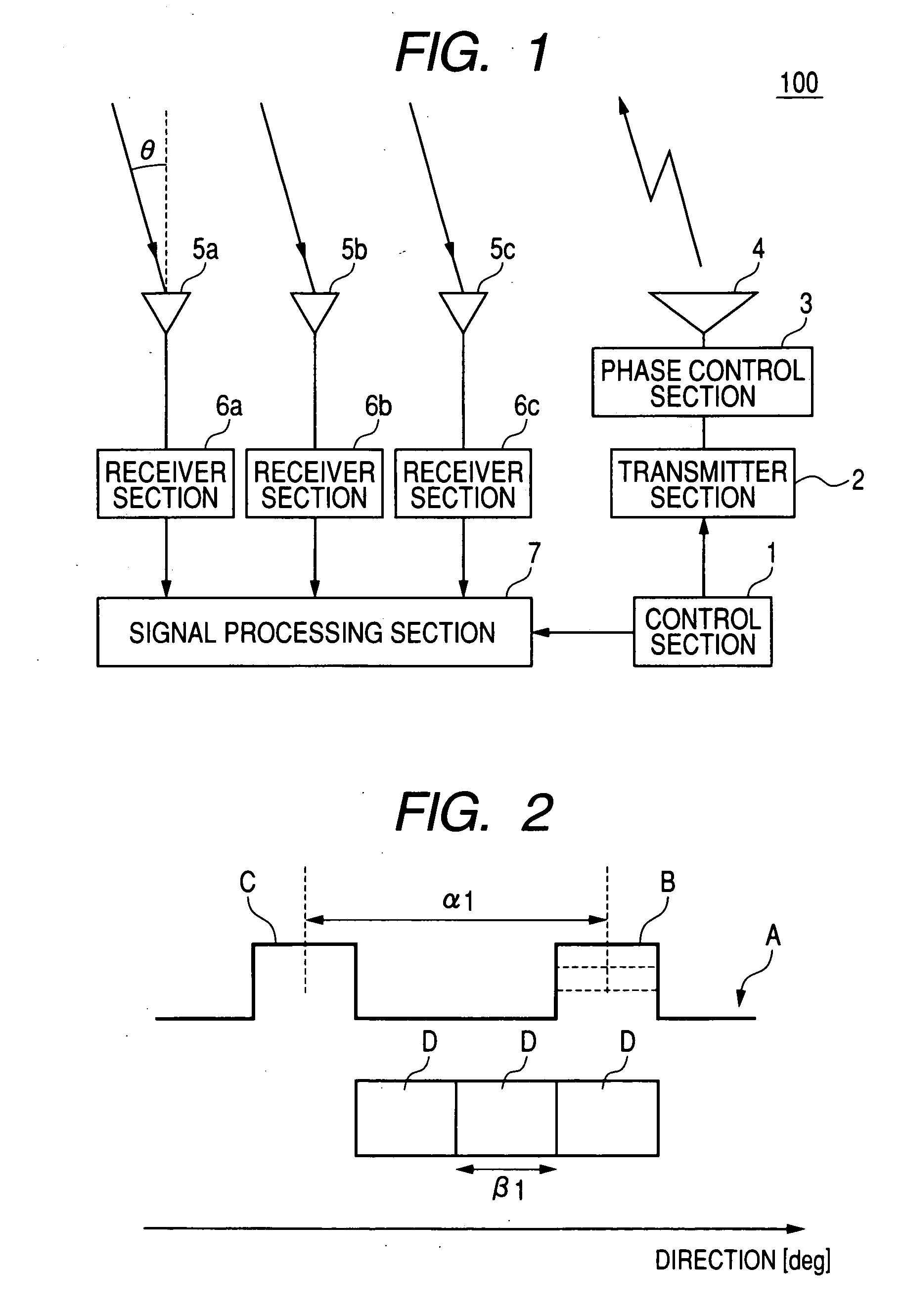
[0082]With the first embodiment described above, a target can be detected within a detection range whose extent exceeds one foldover period β1. However the invention is equally applicable if the detection range does not exceed β1.

[0083]In that case too, effects of grating lobes upon target direction detection can be eliminated, i.e., similar effects to those described above can be obtained for a radar apparatus having an electronic scanning transmitting antenna and a plurality of receiving antennas, if the antennas are configured such that the relationship α1=(k×β1) is satisfied, where (01 between respective directions of the main lobe and a grating lobe of the transmitted beam, but is no greater than α1. That is, the pitch of the elements of the transmitting array antenna and the pitch of the receiving antennas are respectively determined such as to satisfy that relationship, as described for the first embodiment.

[0084]With such a radar apparatus...

second embodiment

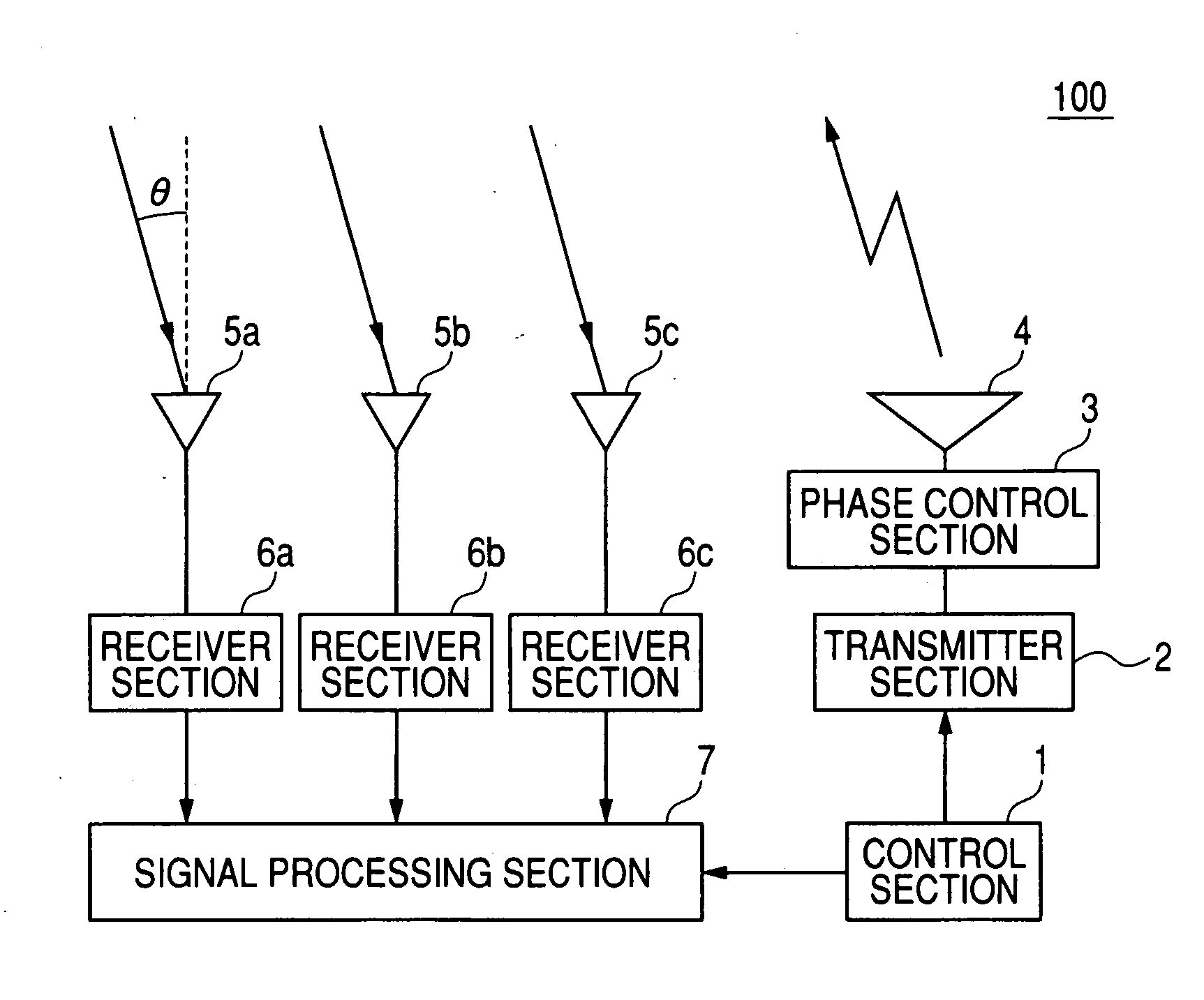
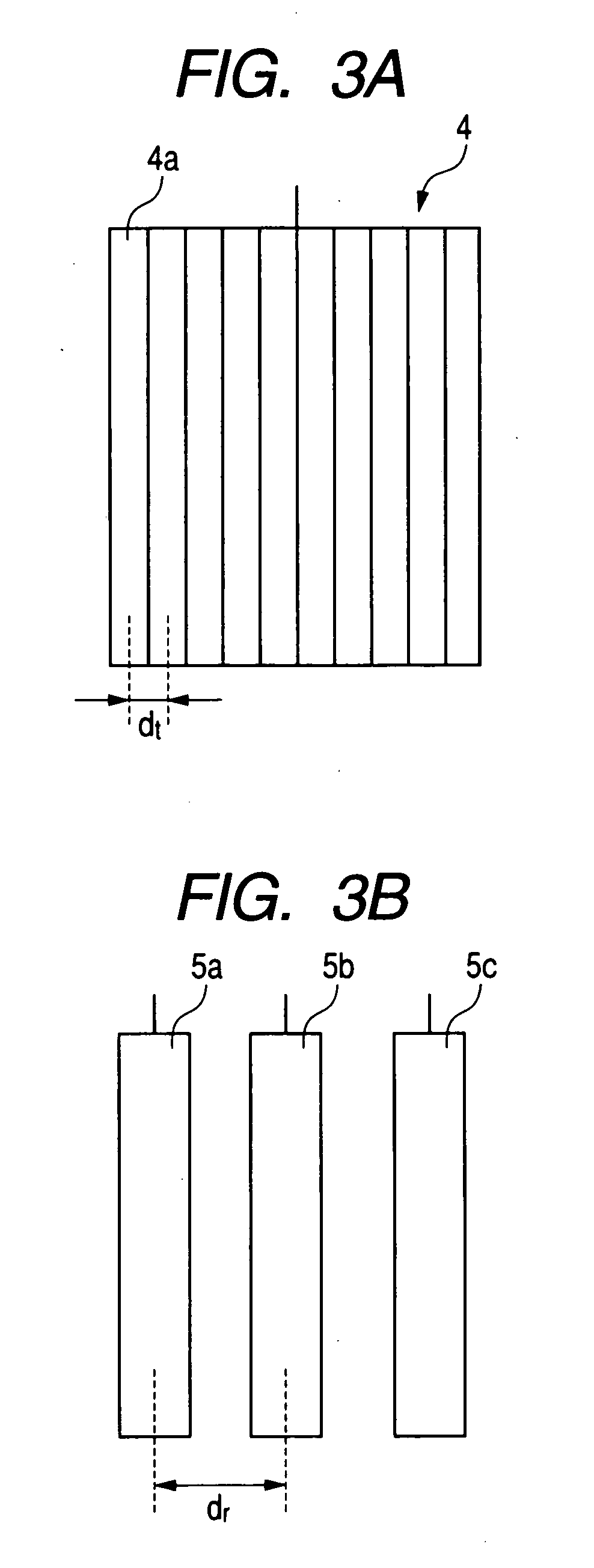
[0086]A second embodiment will be described, which employs similar principles to those of the first embodiment above for suppressing adverse effects of grating lobes upon target direction detection. Only the features of difference with respect to the first embodiment will be described. With the first embodiment, the pitch of the elements constituting the transmitting antenna 4 (array antenna) and the pitch of a plurality of equidistantly-spaced receiving antennas 5a, 5b, 5c are respectively determined such as to satisfy a predetermined relationship, for suppressing the effects of grating lobes in the beam pattern of the transmitting antenna. With the second embodiment, a plurality of transmitting antennas are utilized, spaced apart with a fixed pitch, while the receiving antenna is an array antenna.

[0087]In that case, the directivity characteristic of the receiving antenna is controlled by appropriate phase control of the received signals from the elements of the receiving antenna (...


PUM


Abstract

A radar apparatus has a plurality of receiving antennas and an array transmitting antenna controlled to successively vary the direction of a transmitted beam within a range which includes a target detection range of directions. The direction of any target within the target detection range is detected based on a phase difference between incident reflected waves of adjacent receiving antennas. To eliminate false targets resulting from aliasing, each detected target is authenticated based upon closeness of its detected direction to the current transmitted beam direction. The receiving antennas and transmitting antenna are configured to exclude directions of grating lobes of the transmitted beam from the detection range, and thereby suppress effects of received reflected waves that originate from grating lobes.

Description

CROSS-REFERENCE TO RELATED APPLICATIONS[0001]This application is based on and incorporates herein by reference Japanese Patent Application No. 2009-051259 filed on Mar. 4, 2009.BACKGROUND OF THE INVENTION[0002]1. Field of the Invention[0003]The present invention relates to a radar apparatus for detecting the direction of a target based upon reflected electromagnetic waves, and in particular to a radar apparatus having a plurality of receiving antennas and an array transmitting antenna, or a plurality of transmitting antennas and an array receiving antenna.[0004]2. Background of the Invention[0005]Types of radar apparatus are known having a transmitting antenna which transmits a beam of electromagnetic waves, with the direction of a target being detected based upon phase differences between resultant reflected electromagnetic waves received from the target. In the case of a phase monopulse radar apparatus, the reflected waves are received by two receiving antennas, with the direction...

Claims


Application Information

Patent Timeline
IPC IPC(8): G01S13/00
CPCG01S3/48G01S7/35G01S13/4454H01Q3/30G01S13/931G01S2013/0254H01Q3/2647G01S13/4463
Inventor MIZUTANI, AKIYOSHINATSUME, KAZUMA
Owner DENSO CORP
Features
  • Generate Ideas
  • Intellectual Property
  • Life Sciences
  • Materials
  • Tech Scout
  • Unparalleled Data Quality
  • Higher Quality Content
  • 60% Fewer Hallucinations
Learn More