Strip pack device

a technology of strip pack and packing part, which is applied in the direction of packaging, etc., can solve the problems of affecting the operation of the device, the relation to the conveying part becomes a problem, and the weight of the product cannot be tested before the device, so as to achieve the effect of moving even more smoothly

Inactive Publication Date: 2010-09-16
ISHIDA CO LTD
View PDF10 Cites 3 Cited by
  • Summary
  • Abstract
  • Description
  • Claims
  • Application Information

AI Technical Summary

Benefits of technology

[0017]In cases in which the strip pack device comprises an opposite-direction-moving part for moving the grasping section in the generally opposite direction of the draw-in direction when the grasping section begins to move away from the predetermined position, the ends of the articles drawn in by the

Problems solved by technology

Quality testing of weight, seal quality, and the like cannot be performed before the articles manufactured by the devices are attached to the strip.
In this case, where the attaching position is disposed in relation to the conveying part becomes a problem.
For example, placing the attaching position directly below the conveying means necessitates a configuration for withdrawing the conveying part becoming obstructive every time an article is moved directly downward, which complicates the configuration and operation of the device and is therefore a hindrance to accelerating the operation.
If there are wrinkles or creases in the ends of the bagged articles conveyed by the conveying part, they might be visually unattractive and

Method used


Image

  • Strip pack device
  • Strip pack device
  • Strip pack device

Examples


first embodiment

Overall Configuration Of Strip Pack Device

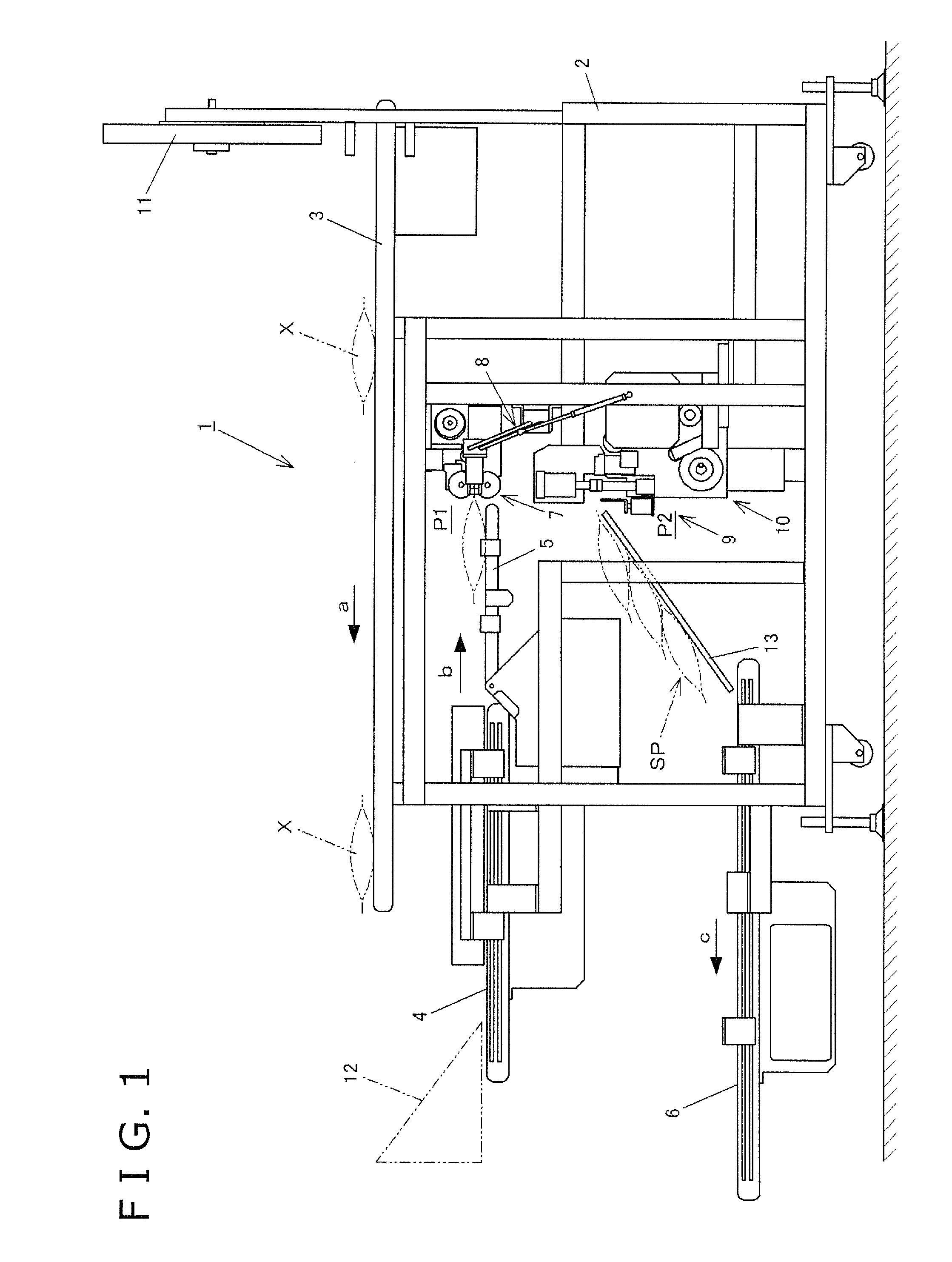
[0034]A strip pack device 1 according to the first embodiment of the present invention comprises a main unit 2, a supply conveyor 3, an induction conveyor 4, a drop conveyor 5, a discharge conveyor 6 (an example of the conveying part), a brush unit 7 (an example of the drawing-in part), grasping units 8 (an example of the moving part), an attachment unit 9 (an example of the attachment part), a tape feed unit 10, a falloff prevention member 12, a cradle 13, and other components, as shown in FIG. 1.

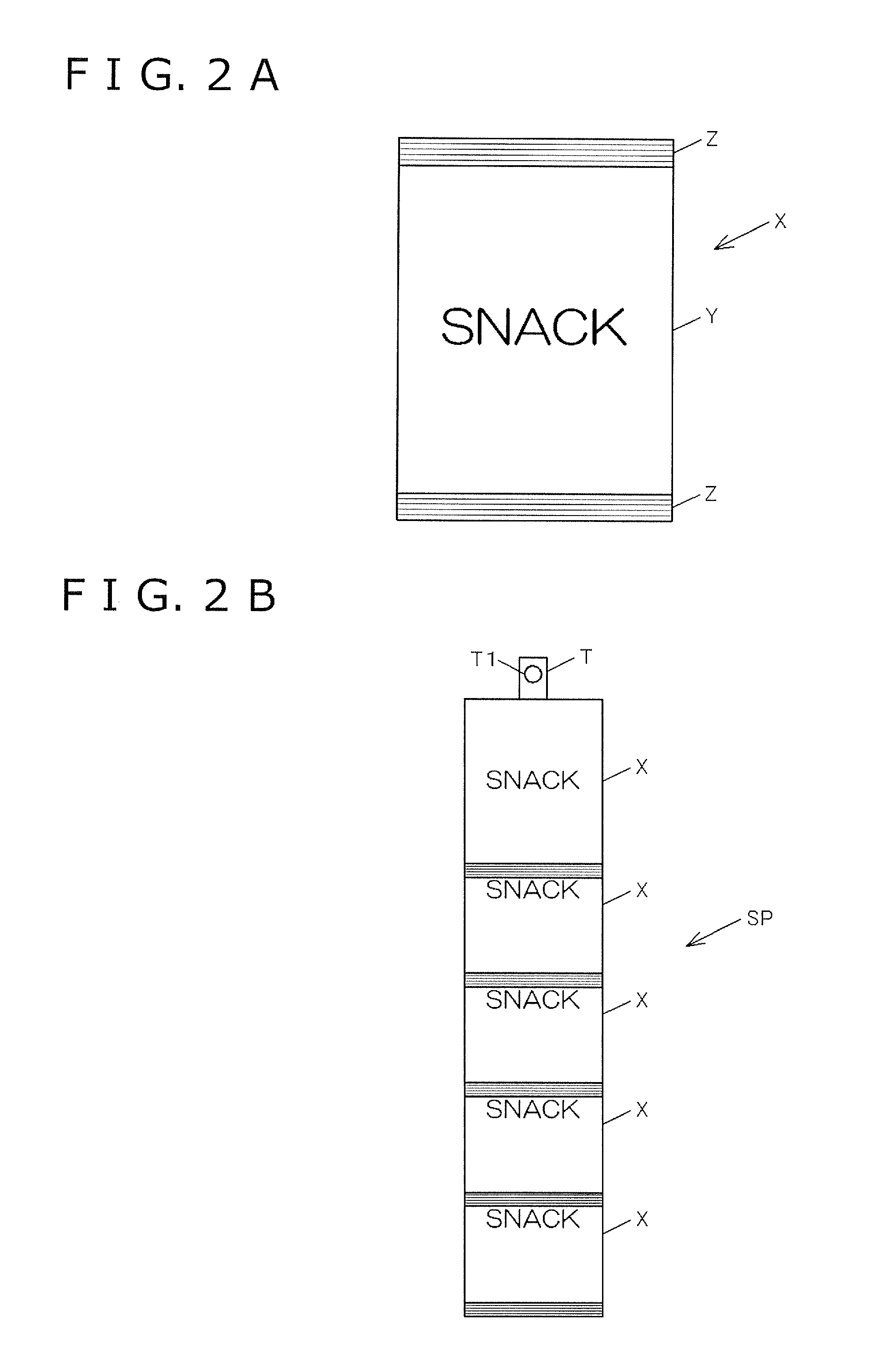
[0035]Bags X filled with, e.g., snack foods or the like are supplied as handled articles to the supply conveyor 3 from an upstream device.

[0036]The induction conveyor 4 guides bags X supplied in the direction of the arrow a by the supply conveyor 3 into the main device 1, as shown by the arrow b.

[0037]The drop conveyor 5 constitutes the terminal end of the induction conveyor 4.

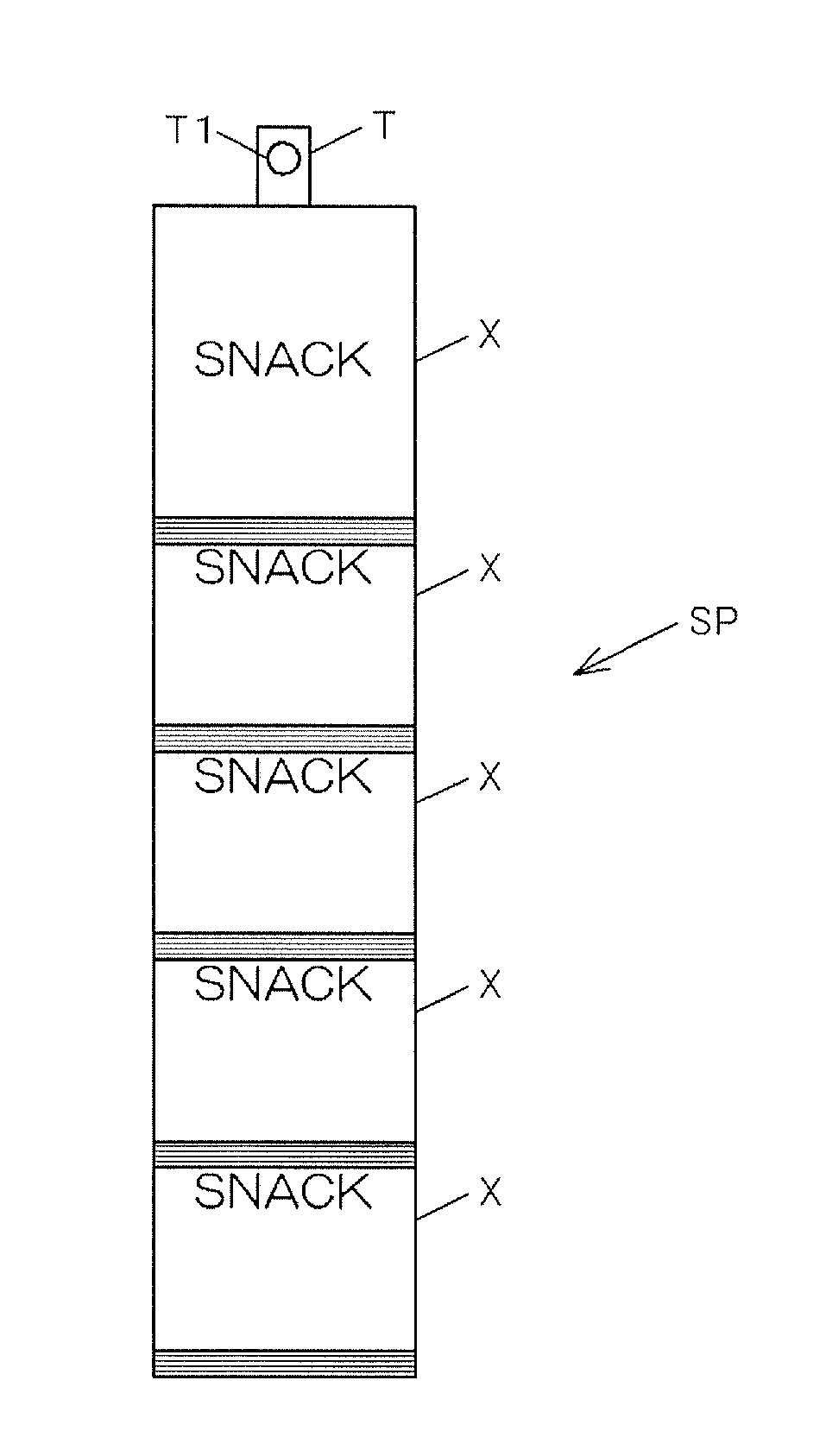
[0038]The discharge conveyor 6 discharges a strip pack SP made of a plur...

second embodiment

[0072]Next, a strip pack device according to the second embodiment of the present invention will be described. Structural elements common to the first embodiment previously described are denoted by the same numerical symbols.

[0073]This strip pack device has the same configuration as the first embodiment except for the grasping units. With these grasping units 108, it is possible to adjust the forward-backward positions of the grip fingers 81, 81 for grasping the sealed parts Z of bags X drawn in by the upper and lower brushes 76, 76 of the brush unit 7, and pneumatic cylinders 188 (an example of the opposite-direction-moving part) are provided for this purpose, as shown in FIG. 8. The grip fingers 81, 81 are attached via hands 82 to the distal ends of rods that reciprocate in the direction of the arrow g, g′ of the pneumatic cylinders 188. The pneumatic cylinders 188 are linked via attachment members 183 to the ends on one side of link members 84, 84, 85, 85 (only one pair on one si...

third embodiment

[0078]Next, a strip pack device according to the third embodiment will be described. Structural elements common to the first embodiment are denoted by the same numerical symbols in this case as well.

[0079]The configuration of this strip pack device is also the same as the first embodiment except for the grasping units. Specifically, the grasping units 208 in this case are disposed farther forward in the conveying direction b than the terminal end of the drop conveyor 5 that pivots around the starting end in the direction of the arrow e, as shown in FIGS. 10 through 12. The grasping units 208 grasp the sealed parts Z in the front of the bags X in the conveying direction from above and below in the front of the conveying direction b, by a pair of upper and lower grip fingers 81, 81, similar to the first embodiment. The grasping units 208 move the grasped bags X from the drawn-in position P1 in the brush unit 7 to the attaching position P2 in the attachment unit 9.

[0080]The grip finger...


PUM


Abstract

A strip pack device is adapted to manufacture a strip-pack product having an article attached to a strip. The strip pack device includes a conveying part, a drawing-in part, a moving part and an attachment part. The drawing-in part is configured and arranged to draw a front end of the article conveyed by the conveying part to a predetermined position. The front end is located frontward in a conveying direction. The moving part is configured and arranged to receive the article at the predetermined position in the drawing-in part, to move the article from the predetermined position in a generally opposite direction of a draw-in direction of the drawing-in part, and to move the article to an attaching position. The attachment part is configured and arranged to attach the front end of the article to the strip after the article has been moved to the attaching position.

Description

[0001]This national phase application claims priority to Japanese Patent Application No. 2007-271955 filed on Oct. 19, 2007. The entire disclosure of Japanese Patent Application No. 2007-271955 is hereby incorporated herein by reference.TECHNICAL FIELD[0002]The present invention relates to a strip pack device for manufacturing a product known as a strip pack, wherein a plurality of articles are attached to a strip and displayed while hanging therefrom, and the present invention pertains to the technological field of article packaging machinery.BACKGROUND ART[0003]There are products known as strip packs, wherein a plurality of articles filled with snack food or the like are aligned on and attached to a strip, that are hung when displayed. The advantage of a strip pack is that less space is needed for the display, and the displays in aisles or other areas of a store, for example, are more likely to be noticed by consumers, which promotes sales.[0004]An example of a strip pack device f...

Claims


Application Information

Patent Timeline
IPC IPC(8): B65B61/00B65B67/00
CPCB65B15/04
Inventor IWAMOTO, YOSHIO
Owner ISHIDA CO LTD
Why Eureka
Try Eureka