Locking Device Using Shape Memory Materials

a technology of shape memory and locking device, which is applied in the direction of mechanical control device, osteosynthesis device, motor, etc., can solve the problems of complex linkage and mechanism to achieve similar functionality, large current electrical device size, and high construction cost of electrical devices, so as to achieve the effect of significantly reducing the energy requirements for activating or deactivating shape memory polymers or shape memory materials, and reducing the overall cost of locking devices

Inactive Publication Date: 2010-09-16
CORNERSTONE RES GROUP
View PDF10 Cites 19 Cited by
  • Summary
  • Abstract
  • Description
  • Claims
  • Application Information

AI Technical Summary

Benefits of technology

[0019]In view of the foregoing needs and problems the present device is used to overcome these problems and meet these needs. By using cheap shape memory polymers and other similar shape memory materials the overall costs of these locking devices can be d

Problems solved by technology

Mechanical systems require complex linkages and mechanisms to accomplish similar functionality.
Solenoids, motors, hydraulic cylinders, valves and other similar types of these approaches are more complex and more expensive to build.
Current electrical devices are typically very large to achieve adequate holding force however; these devices require constant power to maintain the lock resulting in low power efficiency.
Smaller devices cannot obtain the large holding forces necessary for their applications.
Mechanical systems require no power, but their complex design makes them very ex

Method used


Image

  • Locking Device Using Shape Memory Materials
  • Locking Device Using Shape Memory Materials
  • Locking Device Using Shape Memory Materials

Examples


example 1

[0038]A polymeric reaction mixture was formulated by mixing vinyl neodecanoate (7%), divinyl benzene (1%), and styrene (90%) in random order to yield a clear solution. Benzoyl peroxide (2%) was then added to the resulting solution (all composition % are by weight). The resulting solution was kept cold in a refrigerator before use. To prepare the shape memory polymer (SMP), the reaction mixture formulated above was placed in a flat mold. The mixture is then heated in an oven maintained at atmospheric pressure and a temperature of 75° C. for 24 hours. After the material is cured for the specified period of time, it is removed from the oven and allowed to dry and cool down to room temperature. The material is removed from the mold and cut into the desired shapes.

example 2

[0039]A polymeric reaction mixture was formulated by mixing vinyl neodecanoate (7%), divinyl benzene (1%), and styrene (60%) in random order to form a colorless solution. Polystyrene granules (30%) were then added to the resulting solution. The resulting mixture was then allowed to sit at room temperature with occasional stirring until all the polystyrene granules were dissolved to give a clear, viscous solution. Benzoyl peroxide (2%) was then added to the resulting solution (all composition % are by weight). The resulting mixture is ultrasonicated at room temperature for 15 minutes to yield a clear solution. The resulting solution is kept cold in a refrigerator before use. To prepare the shape memory polymer (SMP), the reaction mixture formulated above was placed in a flat mold. The mixture is then heated in an oven maintained at atmospheric pressure and a temperature of 75° C. for 24 hours. After the material is cured for the specified period of time, it is removed from the oven a...


PUM


Abstract

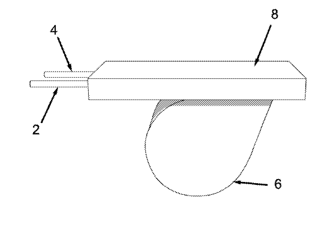
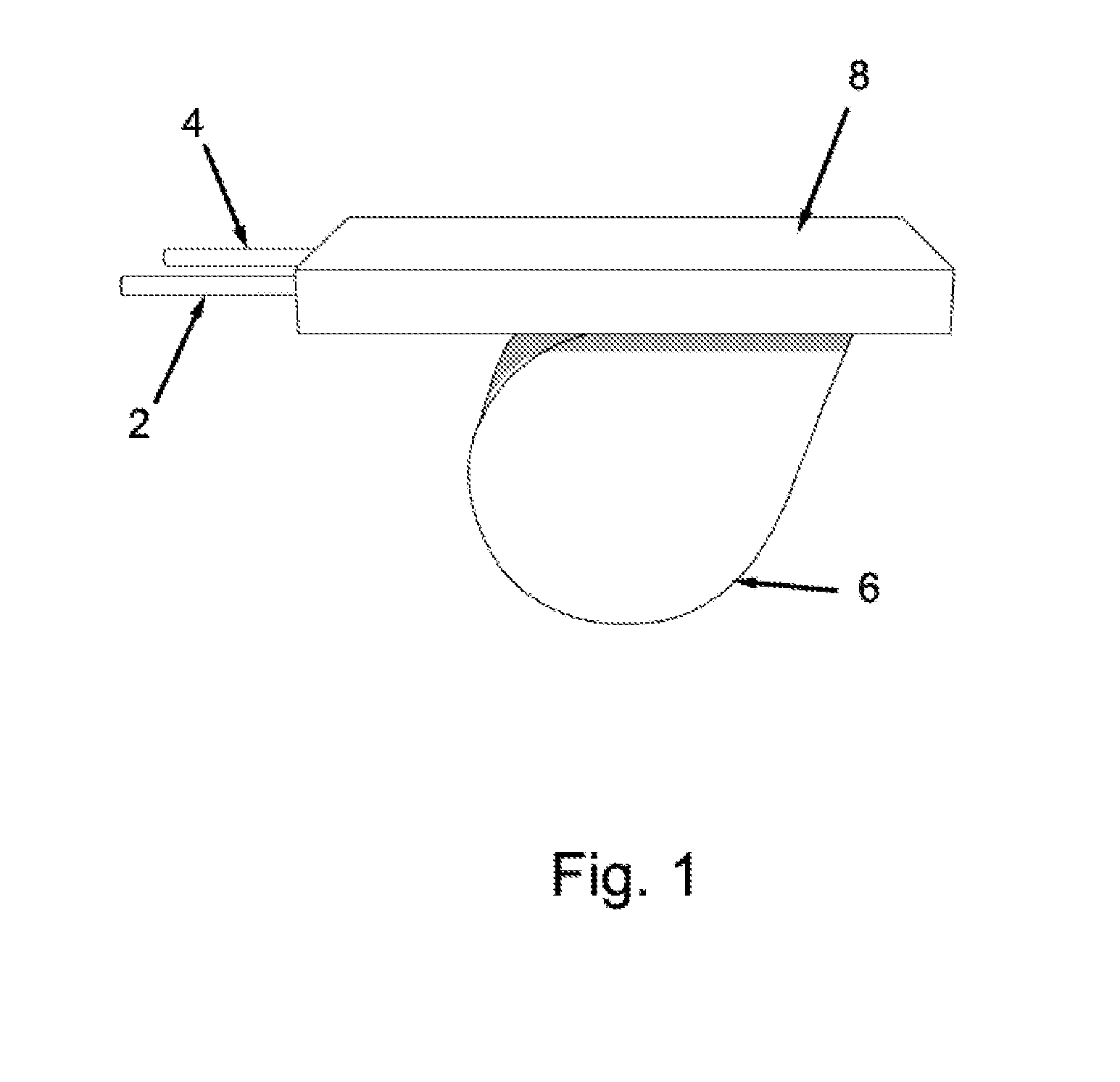
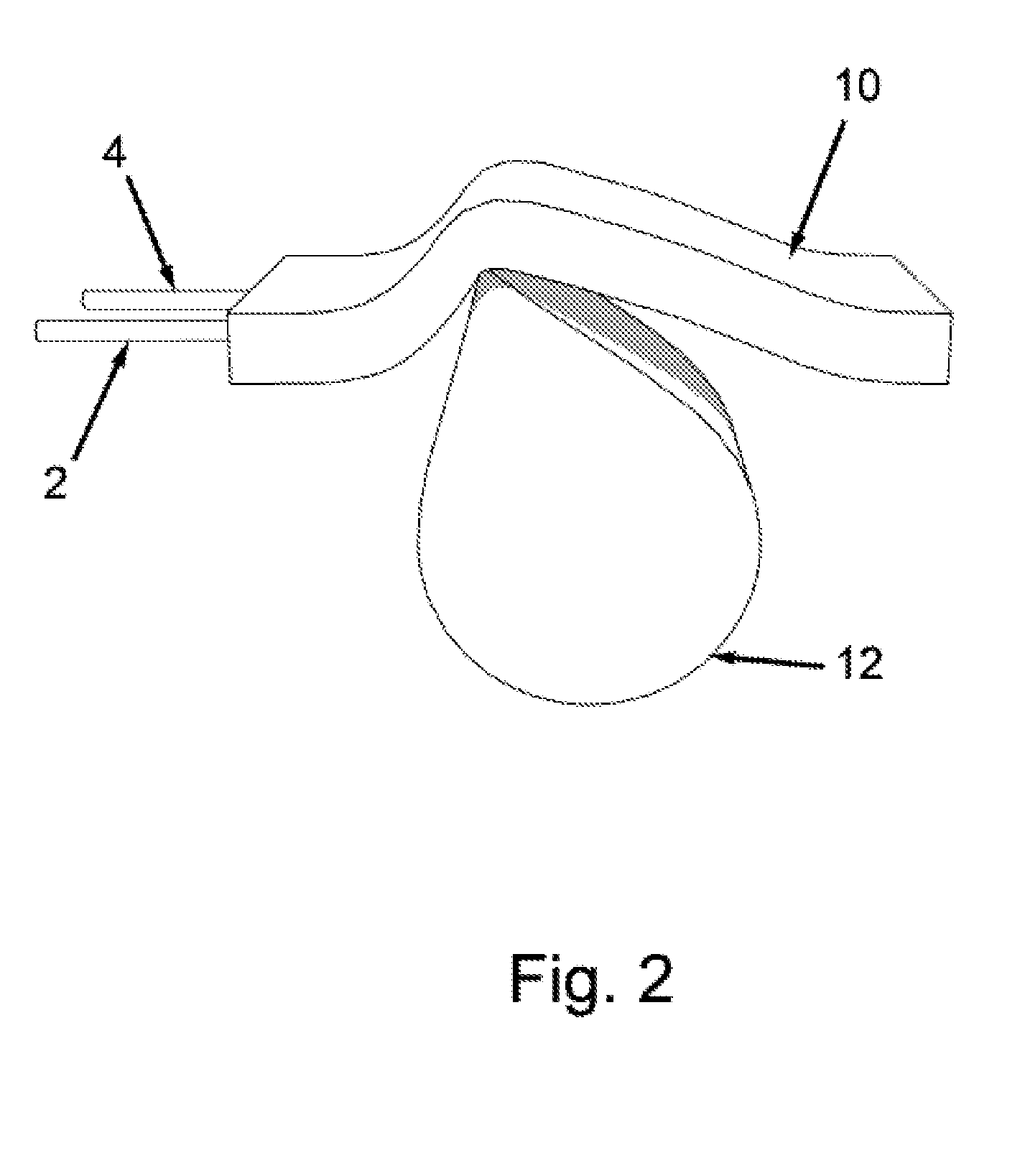
The disclosed devices use shape memory materials, and specifically shape memory polymers and composites to allow or disallow mechanical or physical movement. By positioning the shape memory polymer so it is near the mechanical device which is to be moved, the shape memory polymer will allow or disallow the motion of the mechanical device depending on the state the shape memory polymer is in. When the shape memory polymer is in its hard rigid state the device cannot move. Once activated the shape memory polymer will become soft and pliable, whereupon with sufficient force the mechanical device can be moved to a new position. Once in this new position the SMP can either remain in its relaxed state, the SMP can return to a hard rigid state and maintain its deformed shape, or the SMP can return to its original shape to ensure the device does not move.

Description

CROSS REFERENCE TO RELATED APPLICATIONS[0001]This application claims priority from U.S. Provisional Application Ser. No. 60 / 805,627 filed Jun. 23, 2006.STATEMENT REGARDING FEDERALLY SPONSORED RESEARCH[0002]This application was made in part with government support under contract number FA8650-05C-5047 awarded by the United States Air Force DET 1 AF Research Laboratory. The government may have certain rights in this application.BACKGROUND OF THE INVENTION[0003]Mechanical systems require complex linkages and mechanisms to accomplish similar functionality. Solenoids, motors, hydraulic cylinders, valves and other similar types of these approaches are more complex and more expensive to build. Current electrical devices are typically very large to achieve adequate holding force however; these devices require constant power to maintain the lock resulting in low power efficiency. Smaller devices cannot obtain the large holding forces necessary for their applications. Mechanical systems requi...

Claims


Application Information

Patent Timeline
IPC IPC(8): E05B65/00
CPCE05B47/0009A61B2017/8655Y10T70/5611
Inventor GARRIGAN, SEAN PATRICKHAVENS, TERESA ELLENHAVENS, DAVID ERNEST
Owner CORNERSTONE RES GROUP
Why Eureka
Try Eureka