

Muffler
- Summary
- Abstract
- Description
- Claims
- Application Information
AI Technical Summary
Benefits of technology
Problems solved by technology
Method used
Image

Examples
first exemplary embodiment
[0030]A first exemplary embodiment of the invention will be described below with reference to the attached drawings.
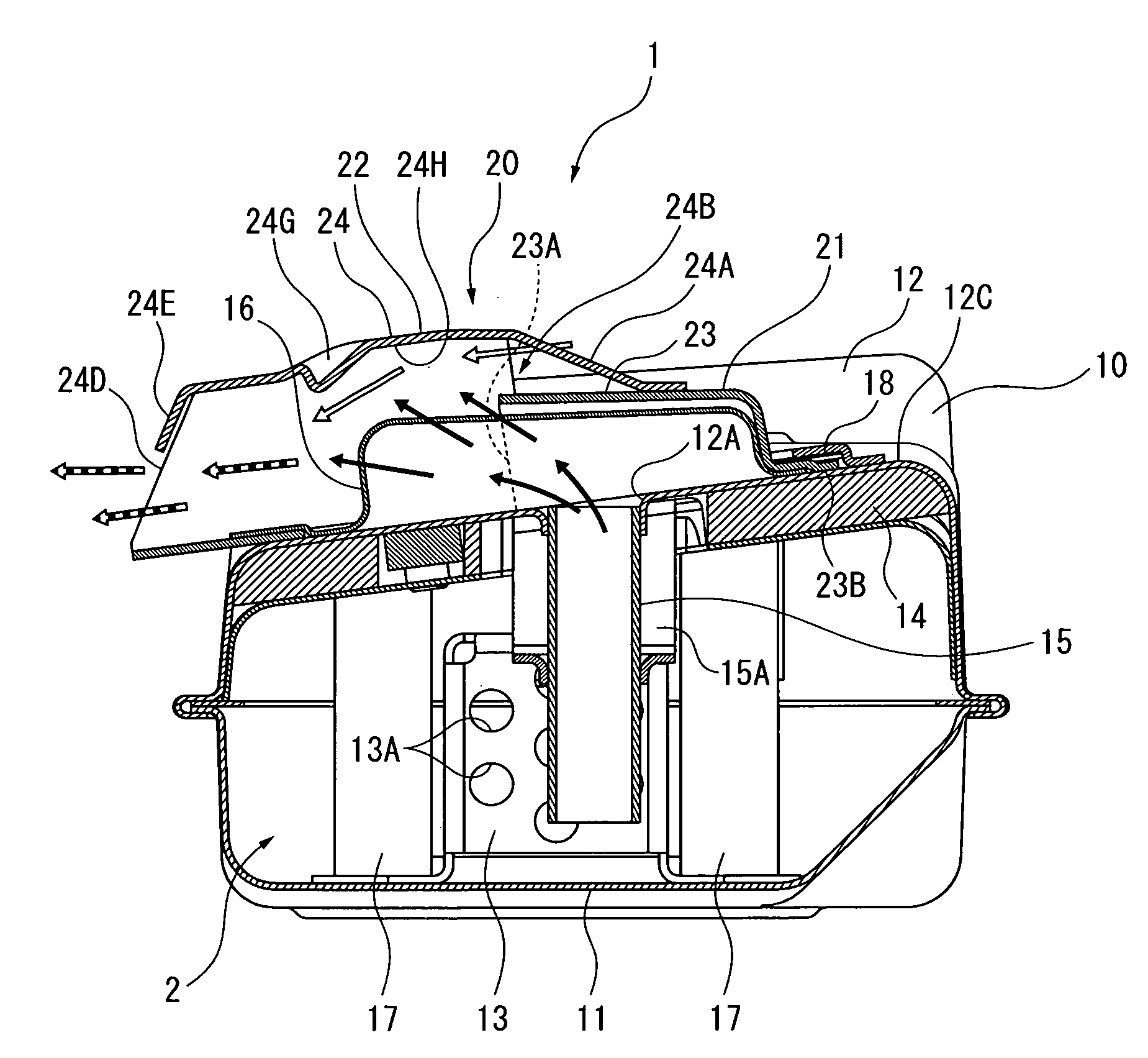
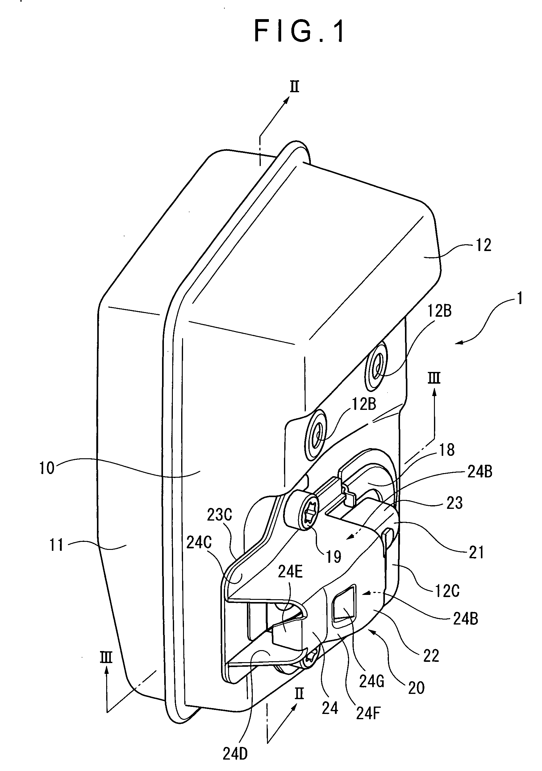
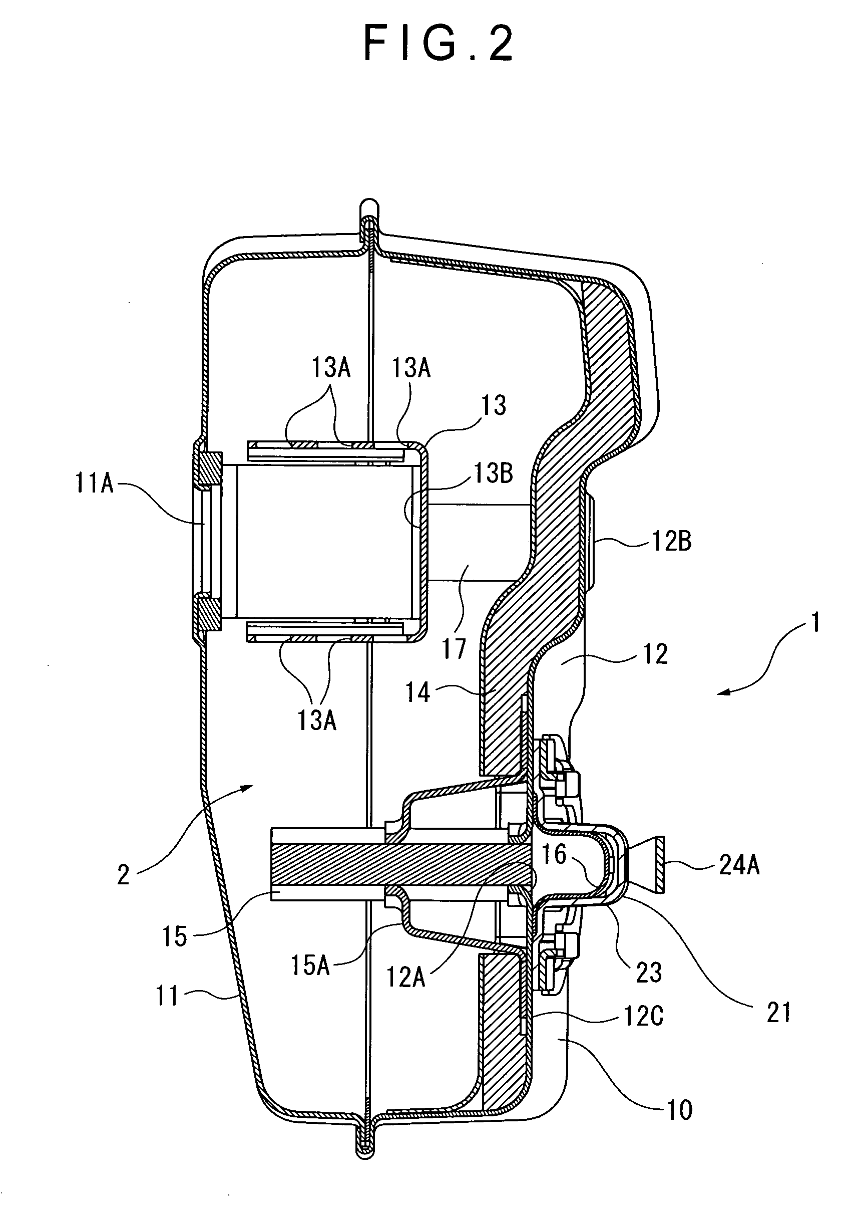
[0031]FIG. 1 is an overall perspective view illustrating a muffler 1 according to the first exemplary embodiment. FIG. 2 is a cross sectional view taken along line II-II of the muffler 1 shown in FIG. 1. FIG. 3 is a cross sectional view taken along line III-III of the muffler 1 shown in FIG. 1. FIG. 4 illustrates an attachment 20 of the muffler 1 in an enlarged manner. FIG. 5 illustrates the attachment 20 shown in FIG. 4 as viewed from a front side. FIG. 6 illustrates the attachment 20 shown in FIG. 4 as viewed from a rear side. As used herein, the front side means a front stream side in a flow direction of exhaust gas, and the rear side means a rear stream side in the flow direction of the exhaust gas.
[0032]The muffler 1 according to the exemplary embodiment is used for a small two-cycle engine mounted on an engine blower (not shown). The muffler 1 includes a box-shap...
second exemplary embodiment
[0056]As shown in FIGS. 9 and 10, in the attachment 20 of a second exemplary embodiment, the height H1 of the discharge port 23A of the exhaust-gas guide member 21 is less than or equal to an inner diameter D1 of the tail pipe 15 (H1≦D1). Other arrangements of this exemplary embodiment are the same as those of the first exemplary embodiment. By such a setting, an ejecting speed of exhaust gas from the discharge port 23A is increased and outer air can be effectively introduced inside due to an improved ejector effect, which favorably lowers temperature of the exhaust gas.
[0057]In this exemplary embodiment, the opening area S1 that is the portion in the narrowest inner space on the front end of the diameter-reduced portion 24F (for example, a portion taken along line IX-IX in FIG. 9, which is orthogonal to the flow direction of exhaust gas; except for the portion including the dent 24G) is four times or more larger than the opening area S2 of the discharge port 23A of the guide 23 (S1...
third exemplary embodiment
[0060]FIGS. 12 to 14 illustrate the muffler 1 and a primary part of the muffler 1 according to a third exemplary embodiment of the invention. In this exemplary embodiment, all conditions L1 / H1≦1, H1≦D1, and S1 / S2≧4 as described in the first and second exemplary embodiments are satisfied.
[0061]In the attachment 20, the mounting piece 23C of the exhaust-gas guide member 21 laterally extends from the muffler body 10 while the mounting piece 24C of the cover hood 22 does not extend so that a length of the cover hood 22 is shortened as a whole. Accordingly, the exhaust port 24D is closer to the outlet 12A as compared with that of the first and second exemplary embodiments. However, even with such an arrangement, since the mounting piece 23C laterally extends, exhaust gas discharged from the exhaust port 24D can be prevented from rolling, which allows a smooth discharge similar to the above exemplary embodiments.
[0062]Also, the cover hood 22 is pressed to be fixed to the exhaust-gas guide...
PUM
 Abstract
Description
Claims
Application Information