Coil component

a coil and component technology, applied in the direction of transformer/inductance details, fixed inductances, inductances, etc., can solve the problem of reducing the strength of connection to the outside, and achieve the effect of inhibiting the downsizing of coil components, and reducing the strength of connection

Active Publication Date: 2017-08-03
MURATA MFG CO LTD
View PDF0 Cites 0 Cited by
  • Summary
  • Abstract
  • Description
  • Claims
  • Application Information

AI Technical Summary

Benefits of technology

[0009]With the downsizing of electronic apparatuses in current years, the further downsizing of coil components is needed. In order to satisfy this need, a method of making the upper wiring electrode patterns 103a and the lower wiring electrode patterns 103b thin and downsizing the pad electrode used for external connection can be considered. However, the downsizing of the pad electrode reduces the strength of connection to the outside. The lead line 105 for connecting the pad electrode and the coil electrode 103 inhibits the downsizing of the coil component 100.

Problems solved by technology

However, the downsizing of the pad electrode reduces the strength of connection to the outside.

Method used


Image

  • Coil component
  • Coil component
  • Coil component

Examples


first embodiment

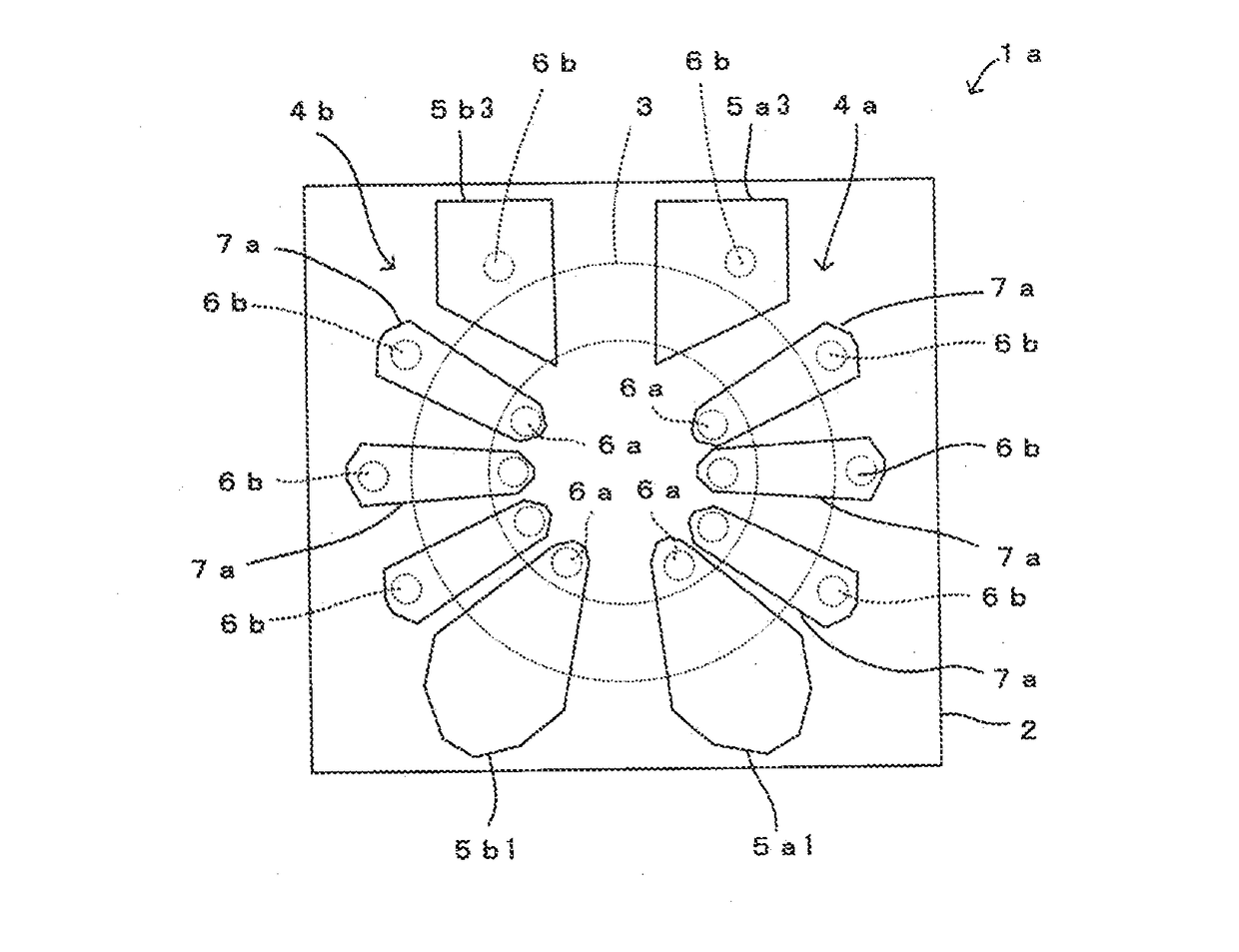
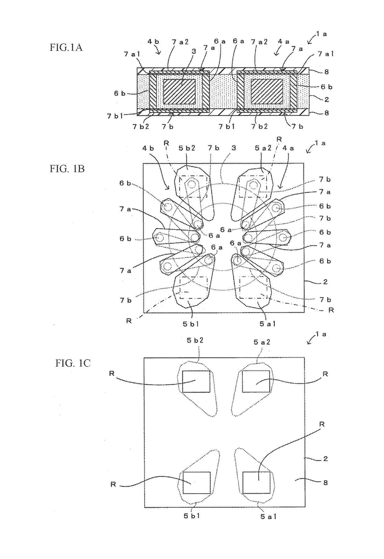
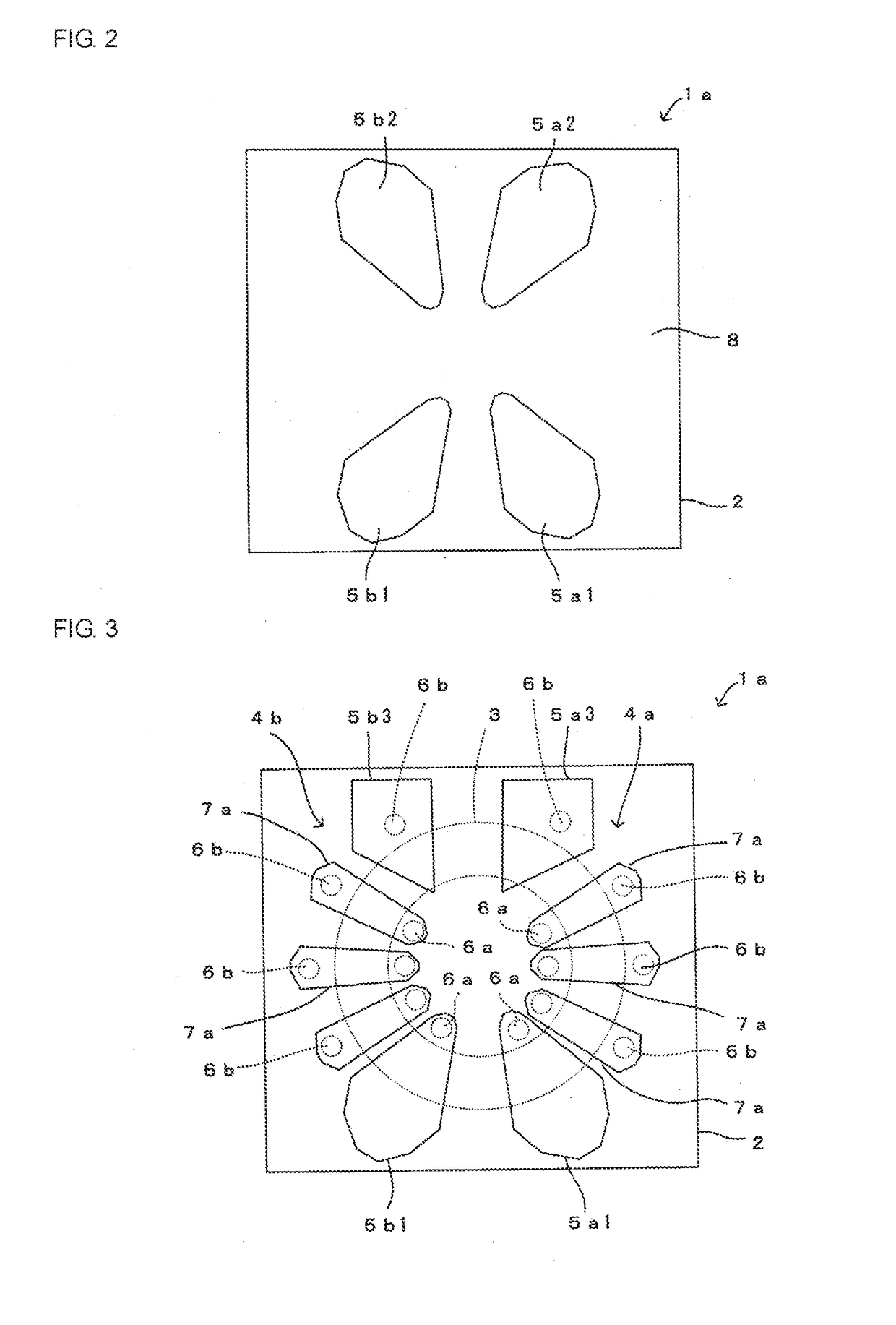
[0028]A coil component 1a according to the first embodiment of the present disclosure will be described with reference to FIGS. 1A, 1B and 1C. FIG. 1A is a cross-sectional view of the coil component 1a. FIG. 1B is a plan view of the coil component 1a in which an insulating film 8 is not illustrated. FIG. 1C is a plan view of the coil component 1a in which the insulating film 8 is illustrated.

[0029]As illustrated in FIGS. 1A to 1C, the coil component 1a according to this embodiment includes an insulating layer 2 in which a magnetic core 3 (corresponding to a “coil core” according to the present disclosure) is embedded, two coil electrodes 4a and 4b wound around the magnetic core 3, and pad electrodes 5a1, 5a2, 5b1, and 5b2 for external connection which are provided on the upper surface (corresponding to a “one main surface” according to the present disclosure) of the insulating layer 2 and are connected to the coil electrodes 4a and 4b. The coil component 1a is mounted on, for exampl...

second embodiment

[0055]A coil component 1b according to the second embodiment of the present disclosure will be described with reference to FIGS. 4A and 4B. FIG. 4A is a plan view of the coil component 1b in which the insulating film 8 is not illustrated. FIG. 4B is a plan view of the coil component 1b in which the insulating film 8 is illustrated. In FIG. 4A, the illustration of the lower wiring pattern 7b is omitted.

[0056]The coil component 1b according to this embodiment differs from the coil component 1a according to the first embodiment described with reference to FIGS. 1A, 1B and 1C in the planar shapes of the pad electrodes 5a4, 5a5, 5b4, and 5b5 as illustrated in FIGS. 4A and 4B. The other configuration of the coil component 1b is the same as that of the coil component 1a according to the first embodiment, and the descriptions thereof will be therefore omitted by assigning the same reference numerals to the corresponding components.

[0057]Unlike the planar shapes of the pad electrodes 5a1, 5a...

third embodiment

[0059]A coil component 1c according to the third embodiment of the present disclosure will be described with reference to FIGS. 5A and 5B. FIG. 5A is a plan view of the coil component 1c in which the insulating film 8 is not illustrated. FIG. 5B is a plan view of the coil component 1c in which the insulating film 8 is illustrated. In FIG. 5A, the illustration of the lower wiring pattern 7b is omitted.

[0060]As illustrated in FIGS. 5A and 5B, the coil component 1c according to this embodiment differs from the coil component 1a according to the first embodiment described with reference to FIGS. 1A, 1B and 1C in that the planar shape of the magnetic core 3 is a track shape, the planar shapes of the upper wiring patterns 7a are reed shapes, and the pad electrodes 5a1, 5a2, 5b1, and 5b2 are rectangular in shape when viewed in a plan view. The other configuration of the coil component 1c is the same as that of the coil component 1a according to the first embodiment, and the descriptions th...


PUM

PropertyMeasurementUnit
thicknessaaaaaaaaaa
areaaaaaaaaaaa
shapeaaaaaaaaaa

Abstract

A coil component includes an insulating layer in which a magnetic core is embedded, coil electrodes wound around the magnetic core, external connection pad electrodes that are provided on the upper surface of the insulating layer and are connected to the coil electrodes. Each of the coil electrodes includes a plurality of inner metal pins standing in the insulating layer, a plurality of outer metal pins standing in the insulating layer, a plurality of upper wiring patterns formed on the upper surface of the insulating layer, and a plurality of lower wiring pattern formed on the undersurface of the insulating layer. Each of the pad electrodes is directly connected to the upper end surface of the inner metal pin or the outer metal pin, and has, in plan view, an area larger than that of the single upper wiring pattern or the single lower wiring pattern.

Description

[0001]This application is a continuation of International Application No. PCT / JP2015 / 078997 filed on Oct. 14, 2015 which claims priority from Japanese Patent Application No. 2014-214970 filed on Oct. 22, 2014. The contents of these applications are incorporated herein by reference in their entireties.BACKGROUND OF THE DISCLOSURE[0002]Field of the Disclosure[0003]The present disclosure relates to a coil component that includes an insulating layer in which a coil core is embedded and a coil electrode wound around the coil core and is connected to the outside.[0004]Description of the Related Art[0005]In electronic apparatuses using high-frequency signals, a coil component including a toroidal coil mounted on a wiring board is sometimes used as a noise canceling component. Since this toroidal coil is relatively large as compared with other components mounted on a wiring board, the toroidal coil takes up a large mount region on the wiring board. In addition, the mounting of a large toroi...

Claims


Application Information

Patent Timeline
Patent Type & Authority Applications(United States)
IPC IPC(8): H01F27/28H01F27/29
CPCH01F27/29H01F27/2804H01F17/0013H01F17/0033H01F17/062H01F27/292
Inventor OTSUBO, YOSHIHITOSAKAI, NORIO
Owner MURATA MFG CO LTD
Why Eureka
Try Eureka