Rotating electrical machine and cooling system of rotating electrical machine

a technology of rotating electrical machines and cooling systems, which is applied in the direction of dynamo-electric machines, electrical apparatus, supports/encloses/casings, etc., can solve the problems of reducing the strength of cooling frames or housings. , to achieve the effect of reducing size and weight and securing strength

Inactive Publication Date: 2016-12-29
HITACHI LTD
View PDF15 Cites 3 Cited by
  • Summary
  • Abstract
  • Description
  • Claims
  • Application Information

AI Technical Summary

Benefits of technology

[0006]In the related art, the total weight of the rotating electrical machine is increased by the amount of the weight of the cooling frame. In regard to this, general methods for reducing size and weight, such as using a light-weight material such as aluminum or carbon fiber for the constituent material of the cooling frame or the housing, or thinning the thickness of the cooling frame or the housing are known. However, in such methods for reducing size and weight, the strength of the cooling frame or the housing is decreased, and thus the cooling frame or the housing is greatly deformed by the load due to the vibration or an increase in temperature during the operation of the rotating electrical machine. Further, if an attachment leg for installing the rotating electrical machine to a pedestal is provided to the housing or the cooling frame, a heat load, which is caused by the difference between the expansion amount of the pedestal and the expansion amount of the rotating electrical machine due to the increase in temperature during the operation of the rotating electrical machine, is concentrated in a connection portion between the attachment leg and the housing or the cooling frame which is reduced in size and weight, and thus the connection strength is decreased.
[0010]According to the invention, by setting the cooling frame to have the partially cylindrical shape, it is possible to provide the rotating electrical machine including the cooling structure capable of obtaining a reduction in size and weight while securing the strength.

Problems solved by technology

However, in such methods for reducing size and weight, the strength of the cooling frame or the housing is decreased, and thus the cooling frame or the housing is greatly deformed by the load due to the vibration or an increase in temperature during the operation of the rotating electrical machine.

Method used


Image

  • Rotating electrical machine and cooling system of rotating electrical machine
  • Rotating electrical machine and cooling system of rotating electrical machine
  • Rotating electrical machine and cooling system of rotating electrical machine

Examples


example 1

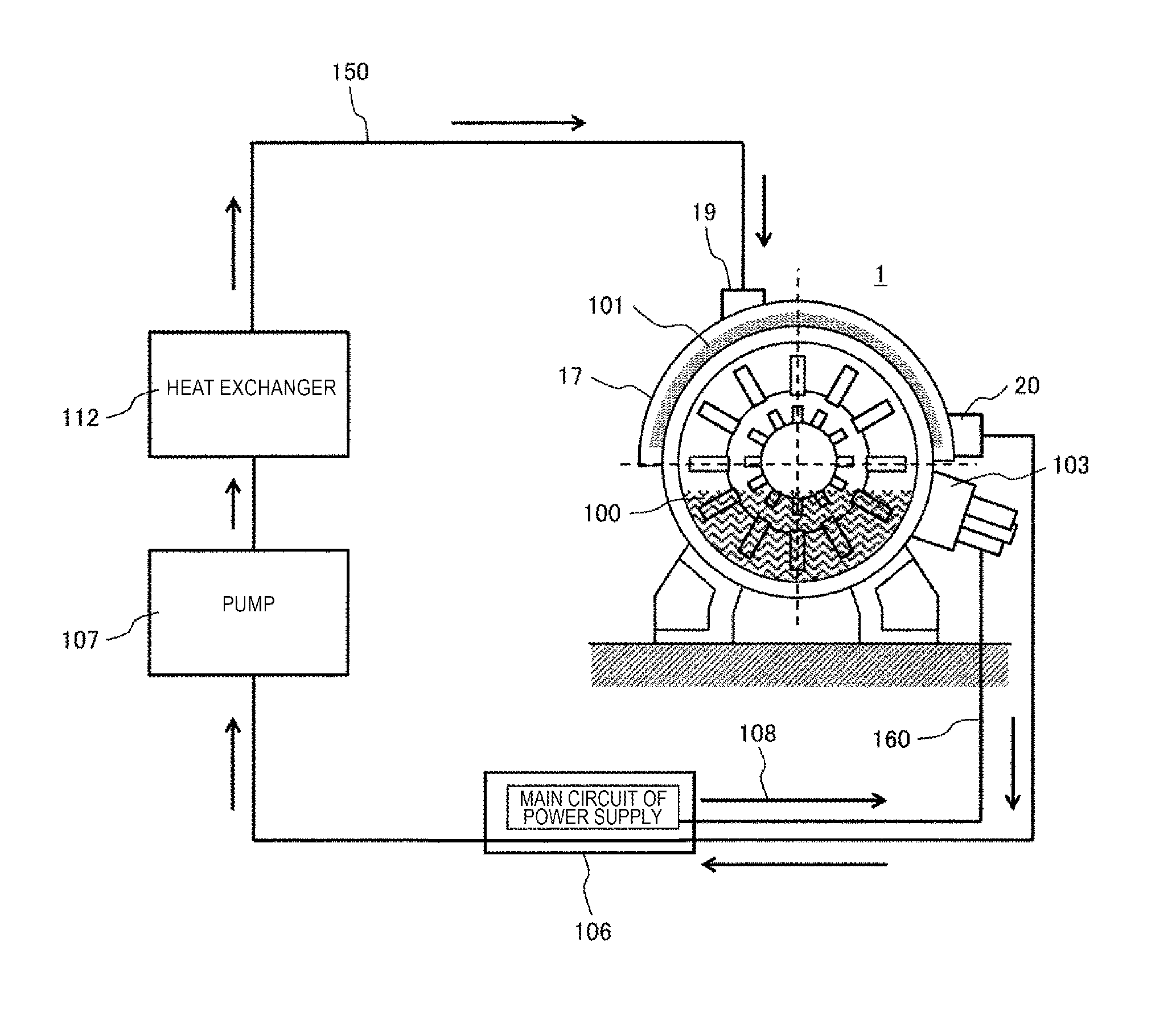
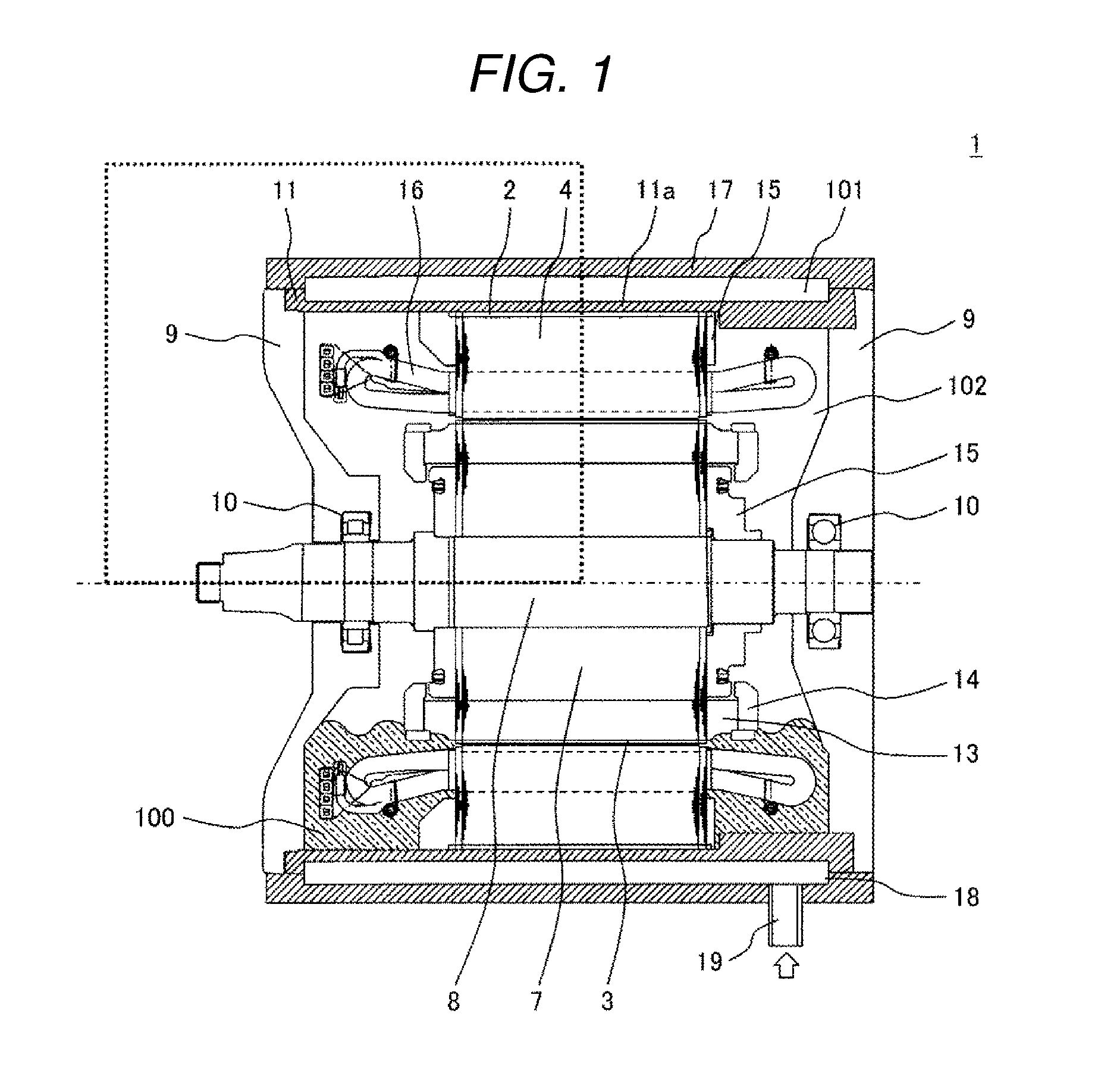
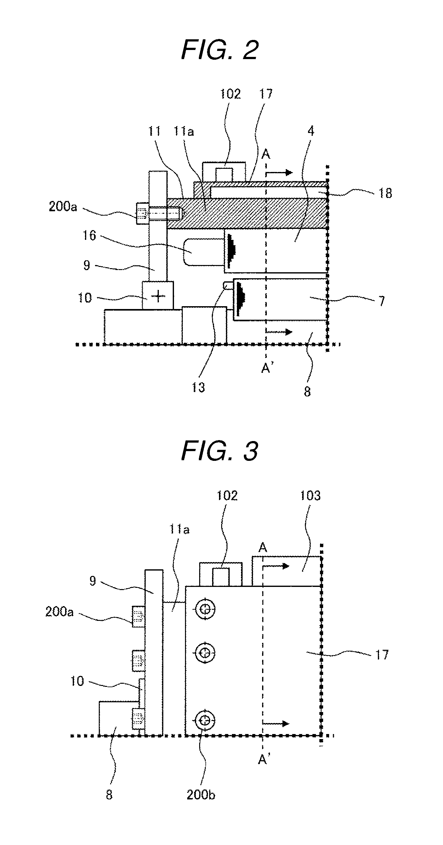
[0028]Example 1 of the invention will be described with reference to FIGS. 1 to 6. FIG. 1 is a sectional view in an axial direction of a rotating electrical machine as Example 1 of the invention. FIG. 2 is a partial sectional view illustrating the vicinity of an end portion in the axial direction of the rotating electrical machine of Example 1. FIG. 3 is a partial side view illustrating the external appearance of the vicinity of the end portion in the axial direction of the rotating electrical machine of Example 1. FIGS. 4A to 4C are sectional views in a direction orthogonal to a rotary shaft of the rotating electrical machine of Example 1. Further, FIGS. 4A to 4C illustrate cross sections respectively taken along line A-A′ in FIG. 2. FIG. 5 is a sectional view in the direction orthogonal to the rotary shaft of a cooling frame 17 of the rotating electrical machine of Example 1. Further, FIG. 5 illustrates a cross section taken along line A-A′ in FIG. 3. FIG. 6 is a partial external ...

example 2

[0047]Next, a rotating electrical machine as Example 2 of the invention will be described. The configuration itself of Example 2 is the same as that of Example 1.

[0048]In Example 2, the cooling frame 17 having a semi-circular shape or a semi-cylindrical shape in Example 1 is attached to the housing 11 at a location where the temperature in a non-cooling state is highest in the circumferential direction of the stator 2 and the rotor 3. Accordingly, the attaching position of the cooling frame 17 in Example 2 can be obtained by shifting the cooling frame 17 from the position in Example 1 in the circumferential direction. In this manner, in the circumferential direction of the rotating electrical machine 1, the peak temperature is decreased and the temperature distribution becomes uniform. Accordingly, unevenness of the temperature may not be considered for the setting of the size or the strength of the cooling frame 17, and thus the size and the weight of the cooling frame 17 can be re...

example 3

[0051]Next, a rotating electrical machine as Example 3 of the invention will be described. The configuration itself of Example 3 is the same as that of Example 1.

[0052]The rotating electrical machine 1 according to Example 3 is used as an air cooling type rotating electrical machine without the cooling frame 17, by using the fact that the cooling frame 17 can be attached or detached without interference with other portions of the rotating electrical machine. In this case, since the attachment legs 102 are provided to the housing 11, the rotating electrical machine according to Example 3 can be installed in the same manner as a case in which cooling is performed by a liquid cooling type rotating electrical machine, by attaching the cooling frame 17 thereto without using other members.

[0053]According to Example 3, a rotating electrical machine capable of being easily applied to both of a liquid cooling type and an air cooling type can be implemented. In addition, if the specifications...


PUM


Abstract

A rotating electrical machine includes a housing having an approximately cylindrical shape; a stator and a rotor that are accommodated in the housing; and a cooling frame that is provided on an outer circumferential surface of the housing and circulates a first liquid refrigerant, in which the cooling frame has a partially cylindrical shape. By setting the cooling frame to have the partially cylindrical shape, it is possible to obtain cooling structure capable of obtaining a reduction in size and weight while securing the strength.

Description

BACKGROUND OF THE INVENTION[0001]Field of the Invention[0002]The present invention relates to a rotating electrical machine including a stator and a rotor, and particularly to a rotating electrical machine cooled by using a refrigerant and a cooling system of a rotating electrical machine.[0003]Background Art[0004]By efficiently cooling a rotating electrical machine by using a liquid refrigerant, it is possible to suppress an increase in size of the rotating electrical machine, and to increase the power output of the rotating electrical machine. As the related art for cooling the rotating electrical machine, technologies described in JP-A-2003-199291 and JP-A-2010-206993 have been known.[0005]In the technologies described in JP-A-2003-199291 and JP-A-2010-206993, the rotating electrical machine is cooled by circulating the liquid refrigerant in a cooling frame attached to the rotating electrical machine. Here, a housing in which a stator and a rotor are stored, and the cooling frame...

Claims


Application Information

Patent Timeline
Patent Type & Authority Applications(United States)
IPC IPC(8): H02K5/20H02K9/19H02K5/18
CPCH02K5/20H02K9/19H02K5/18H02K5/203
Inventor IMURA, MAKOTONAKA, YASUHIROSUGIMOTO, SHINJIKORI, DAISUKE
Owner HITACHI LTD
Why Eureka
Try Eureka