
Flexible printed circuit and imaging apparatus including same

a printed circuit and flexible technology, applied in the direction of electrical apparatus casings/cabinets/drawers, television systems, casings/cabinets/drawers details, etc., can solve the problem of low workability in the assembly operation, and achieve the effect of reducing thickness, high insulation properties, and reducing the size of electronic devices

Active Publication Date: 2021-04-06
PANASONIC INTELLECTUAL PROPERTY MANAGEMENT CO LTD
View PDF16 Cites 0 Cited by
  • Summary
  • Abstract
  • Description
  • Claims
  • Application Information

AI Technical Summary

Benefits of technology

The invention aims to provide a flexible printed circuit that meets high insulation standards without increasing its thickness, which would limit the size of electronic devices that use it. The approach uses a special coating that achieves better insulation without adding any weight to the circuit. This makes it easier to assemble and use in smaller electronic devices.

Problems solved by technology

In addition, due to the insulation tape being wound, workability in an assembling operation is low.

Method used


Image

  • Flexible printed circuit and imaging apparatus including same
  • Flexible printed circuit and imaging apparatus including same
  • Flexible printed circuit and imaging apparatus including same

Examples


Embodiment Construction

[0026]Exemplary embodiments will be described in detail below with reference to the drawings. However, unnecessarily detailed descriptions may be omitted. For example, a detailed description of well-known matters, and a duplicate description of substantially identical configurations may not be provided. This is to avoid unnecessary redundancy in the following description and to facilitate understanding of those skilled in the art.

[0027]The inventor of the present disclosure provides the appended drawings and the following description in order to allow those skilled in the art to fully understand the present disclosure, and does not intend to limit the subject matter described in the appended claims by the appended drawings and the following description.

[1-1. Digital Camera]

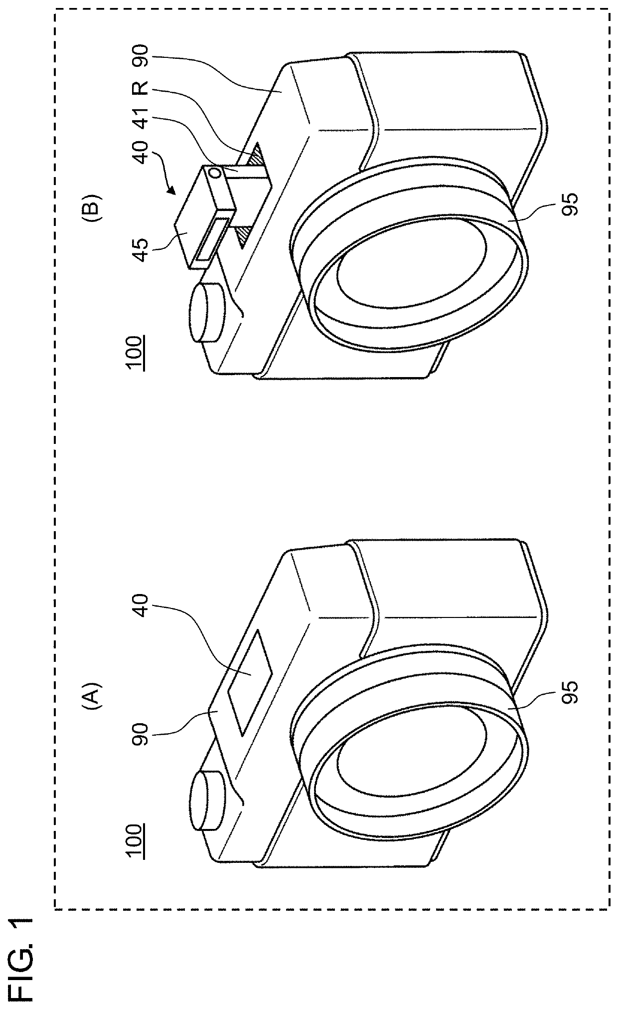
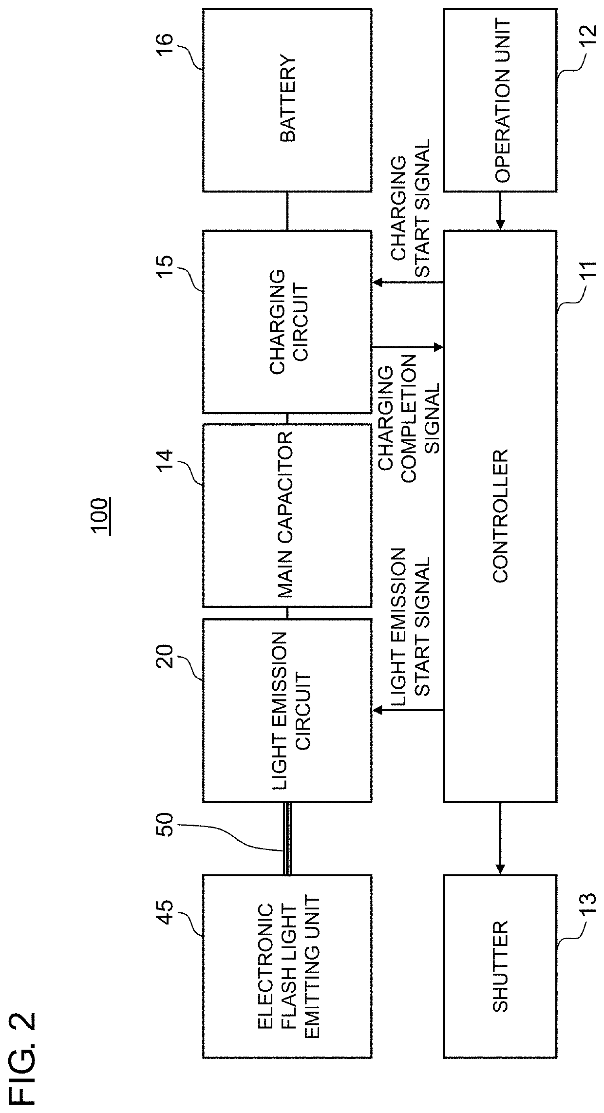
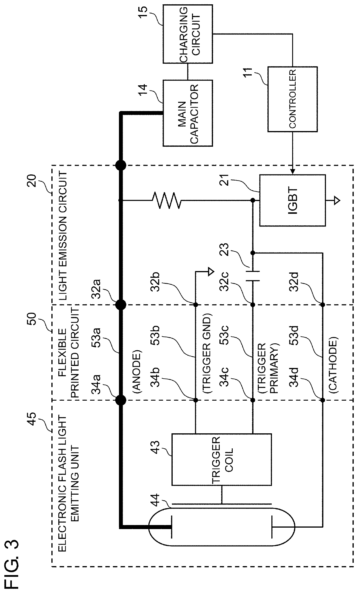
[0028]FIG. 1 is a perspective view of a digital camera including a flexible printed circuit according to an exemplary embodiment of the present disclosure. Digital camera 100 is an apparatus that captures an image...


PUM

PropertyMeasurementUnit
withstand voltageaaaaaaaaaa
voltageaaaaaaaaaa
voltageaaaaaaaaaa

Abstract

The flexible printed circuit includes a first insulator including a first insulating layer, a second insulator including a second insulating layer, and a wiring layer formed of a conductive material. Each of the first insulator and the second insulator meets IEC 60950. The flexible printed circuit includes a region where insulation of the wiring layer is required, the region is hermetically sealed by the first insulator and the second insulator.

Description

BACKGROUND1. Technical Field[0001]The present disclosure relates to a flexible printed circuit and an imaging apparatus including the flexible printed circuit.2. Description of the Related Art[0002]Unexamined Japanese Patent Publication No. 1111-258657 (PTL 1) discloses a camera including an electronic flash light emitting unit in an electronic flash device that emits electronic flash light toward a subject, an image sensor, and an image display device that displays a finder image based on an image signal acquired from the image sensor. This camera also includes a housing into which the image display device is incorporated and which is attached to a camera body so as to be freely raised and lowered. The electronic flash light emitting unit is incorporated in the housing. The camera is configured such that, when the housing is raised, a display surface of the image display device faces rearward of the camera body and an electronic flash light emission surface of the electronic flash ...

Claims


Application Information

Patent Timeline
Patent Type & Authority Patents(United States)
IPC IPC(8): H05K1/18H05K1/14H05K1/02H05K5/02H04N5/235H04N5/225H05K5/06H04N5/335H05K1/03H04N25/00
CPCH05K1/189H04N5/2254H04N5/2256H04N5/2354H04N5/335H05K1/0256H05K1/147H05K5/0247H05K5/06H05K1/0393H05K1/148H05K2201/0129H05K2201/0145H05K2201/0154H05K2201/0195H05K2201/055H05K2201/10121H04N23/55H04N23/56H04N23/74H04N25/00
Inventor KASUGAI, HIROKI
Owner PANASONIC INTELLECTUAL PROPERTY MANAGEMENT CO LTD
Learn More