Anti-siphon trap with snorkel

a technology of snorkel and anti-siphon trap, which is applied in the direction of separation process, transportation and packaging, filtration separation, etc., can solve the problems of affecting affecting the flow of wastewater, and causing problems, etc., to achieve the effect of improving the flow or channeling of wastewater and reducing the area of sealan

Active Publication Date: 2010-09-16
FALCON WATERLESS TECH INC
View PDF8 Cites 7 Cited by
  • Summary
  • Abstract
  • Description
  • Claims
  • Application Information

AI Technical Summary

Benefits of technology

[0008]These and other problems are successfully addressed and overcome by the present invention. The ceiling of the entry compartment is lowered and a throat or other small entry is positioned between the cartridge opening and the entry compartment ceiling, so as to reduce the area

Problems solved by technology

Syphoning is a significant problem with waterfree traps.
Unfortunately, such dumping can overwhelm the ability of the drain stand or drain tube to receive the excess water, such as by completely filling the discharge or outlet compartment to its ceiling, thus creating a syphon effect, which thereby sucks the wastewater and sealant from the entry compartment.
This problem can be created also by other events, such as through a sudden and heavy use.
Regardless of the form of the event, the sealant is lost and, with it, its odor fighting capability.
Furthermore, when sealant is lost thr

Method used


Image

  • Anti-siphon trap with snorkel
  • Anti-siphon trap with snorkel
  • Anti-siphon trap with snorkel

Examples


Embodiment Construction

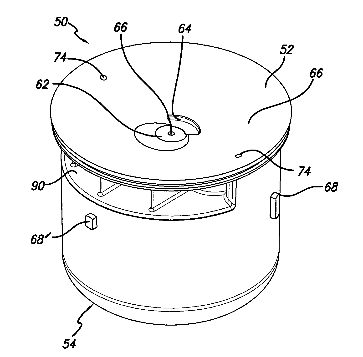
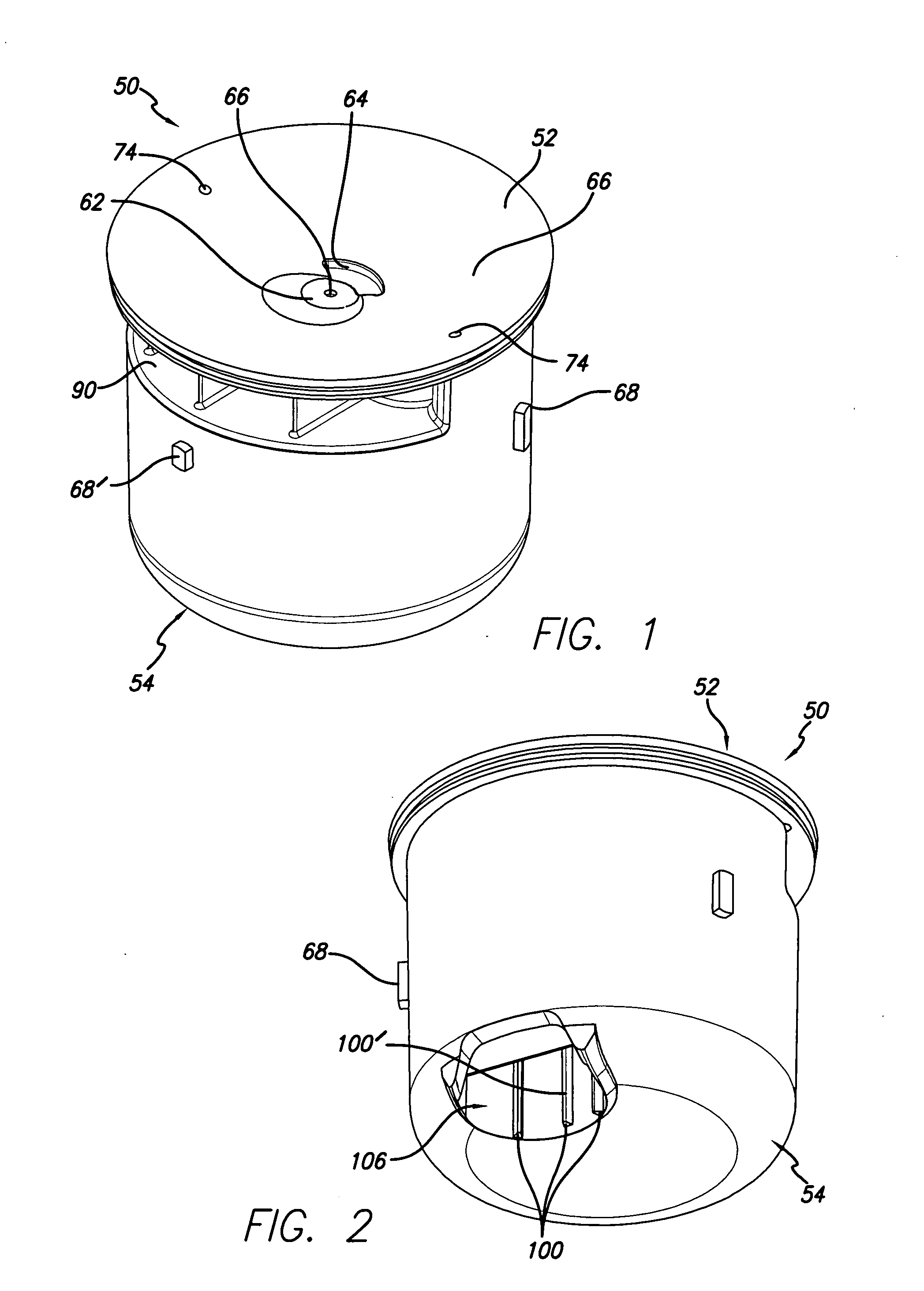
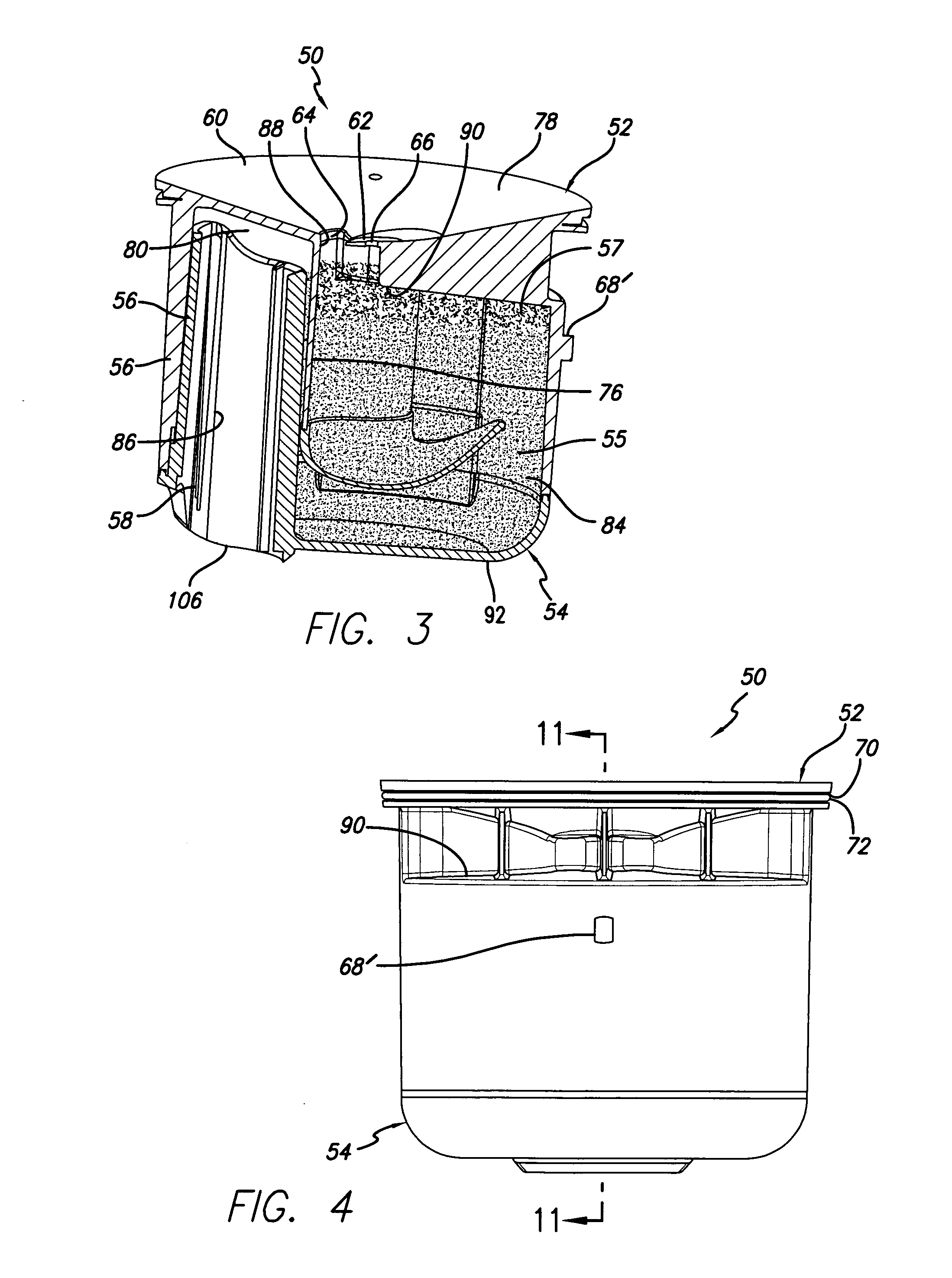
[0063]Accordingly, as illustrated in FIGS. 1-18, a cartridge 50, such as capable of being inserted into a urinal housing, includes a top or top portion 52 and bottom or bottom portion 54. Such a cartridge is sometimes referred to as an “oil sealant-preserving drain odor trap.” Cartridge 50 is capable of acting as a flow trap for urine or other generally fluid waste products. As shown in FIGS. 3, 11 and 11A, wastewater 55, such as a fluid with urine therein, and an oily liquid odor sealant 57 floating on the wastewater is contained within the cartridge, as described in above-cited application Ser. No. 11 / 812,242, No. 60 / 878,635, Ser. No. 11 / 032,310 and Ser. No. 11 / 032,508.

[0064]With reference also to FIGS. 19-28, top portion 52 has a cylindrical configuration defined by a tubular wall 56 terminated by an opening 58 at its lower end and a top wall 60 at its upper end. The top wall is sloped downwardly from its outer edge to a flat, generally horizontal flat center portion 62 in which ...


PUM

PropertyMeasurementUnit
Flow rateaaaaaaaaaa
Areaaaaaaaaaaa

Abstract

The amount of sealant needed as an odor barrier in a wastewater cartridge is reduced. The cartridge inlet compartment (78) has a ceiling (90) of given area. The ceiling is spaced from the cartridge upper wall (60) and from the wastewater-receiving opening (64) therein. A throat (88), which communicates the inlet compartment with the wastewater-receiving opening, has an area which is less than the area of the ceiling, so that the amount of the sealant acting as the barrier, as contained within the throat, is less than any further amount of the sealant (under the ceiling) which floats on the wastewater in the inlet compartment. Also, should sealant not be present within the throat to act as an odor barrier, only a small area of wastewater present within the throat would be exposed to the air external to the cartridge and, thus, present a lesser opportunity of odor to emanate to the outside environment. Further, a discharge section (86) is coupled between an outlet compartment (80) and the external drain and includes a drain tube (98) having walls surrounding a center and communicating with the outlet compartment and opens at an exit port area (106) for discharge of the wastewater fluid from the outlet compartment to the drain. A three rib channel guide mechanism (100) is formed within the tube to guide flow of the wastewater towards the drain tube center, and away from the drain tube walls to avoid deposit of any sediment contained in the wastewater. In addition, the discharge section drain tube (98) includes a snorkel (110) which extends downwards to above the level of the horizontal drain, to allow any air from the external drain to pass to the outlet compartment generally below the ceiling (90) so that, should wastewater cover the opening of the drain tube, such air is permitted to enter into the cartridge and to prevent any syphoning.

Description

CROSS-REFERENCE TO RELATED APPLICATION[0001]This application claims the benefit of U.S. Provisional Application No. 61 / 210,115 filed 12 Mar. 2009, and U.S. application Ser. No. 11 / 812,242, filed 16 Jun. 2006, entitled “Urinal Cartridge with Increased Sediment Collection” and No. 60 / 878,635, filed 3 Jan. 2007, entitled “Urinal Cartridge with Improved Performance.” Subsidiary benefit is also claimed in U.S. application Ser. No. 11 / 032,310 (now U.S. Pat. No. 7,571,741 dated 11 Aug. 2009) and Ser. No. 11 / 032,508 (now U.S. Pat. No. 7,575,022 dated 18 Aug. 2009), both filed 9 Jan. 2005, and the applications upon which they claim benefit.REFERENCE REGARDING FEDERAL SPONSORSHIP[0002]Not ApplicableREFERENCE TO MICROFICHE APPENDIX[0003]Not Applicable[0004]1. Field of the Invention[0005]The present invention relates to a flow trap, such as a cartridge used in water-free urinals having an odor-preventing oily sealant closure mechanism and, in particular, to improving flow trap life and usabilit...

Claims


Application Information

Patent Timeline
IPC IPC(8): B01D35/157
CPCE03C1/28E03C1/294E03C1/29E03C1/281E03D13/007Y10T137/4463Y10T137/4531E03C1/284E03D13/00
Inventor AVETISIAN, ROBERT
Owner FALCON WATERLESS TECH INC
Why Eureka
Try Eureka