Apparatus for Continuously Manufacturing Stoichiometric Mg2Ni Hydrogen Storage Compound

Active Publication Date: 2010-09-16
NAT CHUNG SHAN INST SCI & TECH
View PDF3 Cites 1 Cited by
  • Summary
  • Abstract
  • Description
  • Claims
  • Application Information

AI Technical Summary

Benefits of technology

[0007]An objective of the present invention is to provide a method and apparatus for manufacturing stoichiometric Mg2Ni hydrogen

Problems solved by technology

However, in practical applications, due to the light molecular weight of hydrogen, the storage volume will be immensely huge.
Though super-high pressure can be adopted for storage, safety will be another issue.
Nevertheless, the hydrogen storage density of current commercial hydrogen storage alloys, including transition-metal-based hydrogen storage alloys AB2 or rare-earth-metal-based hydrogen storage alloys AB5, is still too low, less than 2.0% in weight.
However, because pure magnesium is very active, the surface thereof tends to form an oxidation layer that can block absorption of hydrogen molecules, and hence affect diffusion rate of hydrogen atoms on the surface of alloys.
As a result, pure magnesium is difficult to be activated and has bad hydrogen absorption-desorption dynamics.
In addition, the temperatures of hydrogen absorption and desorption are too high.
Accordingly, it cannot be developed to be a practical hydrogen storage alloy.
Because the melting points of magnesium (649° C.) and nickel (145

Method used


Image

  • Apparatus for Continuously Manufacturing Stoichiometric Mg2Ni Hydrogen Storage Compound
  • Apparatus for Continuously Manufacturing Stoichiometric Mg2Ni Hydrogen Storage Compound
  • Apparatus for Continuously Manufacturing Stoichiometric Mg2Ni Hydrogen Storage Compound

Examples


Embodiment Construction

[0020]In order to make the structure and characteristics as well as the effectiveness of the present invention to be further understood and recognized, the detailed description of the present invention is provided as follows along with preferred embodiments and accompanying figures.

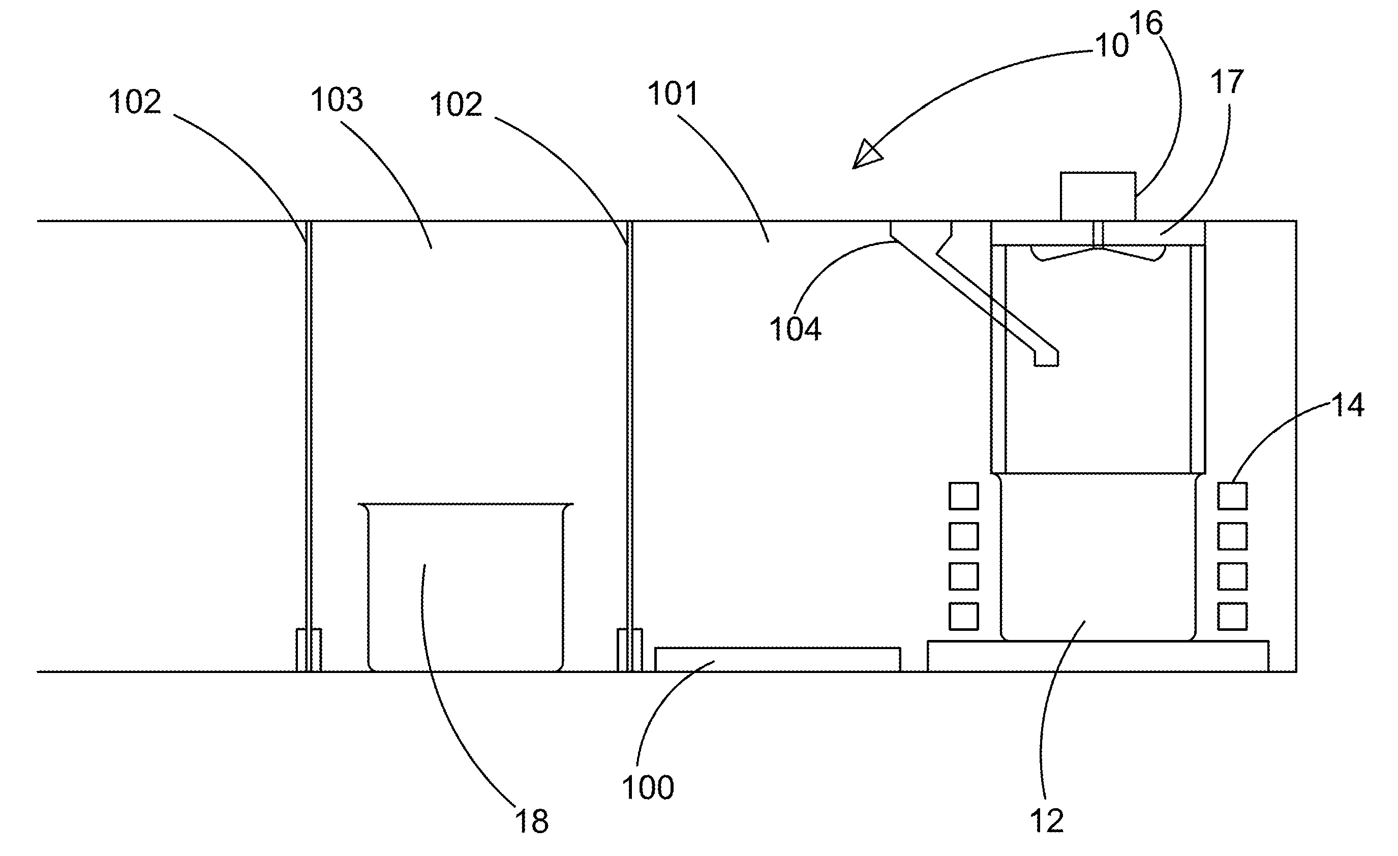
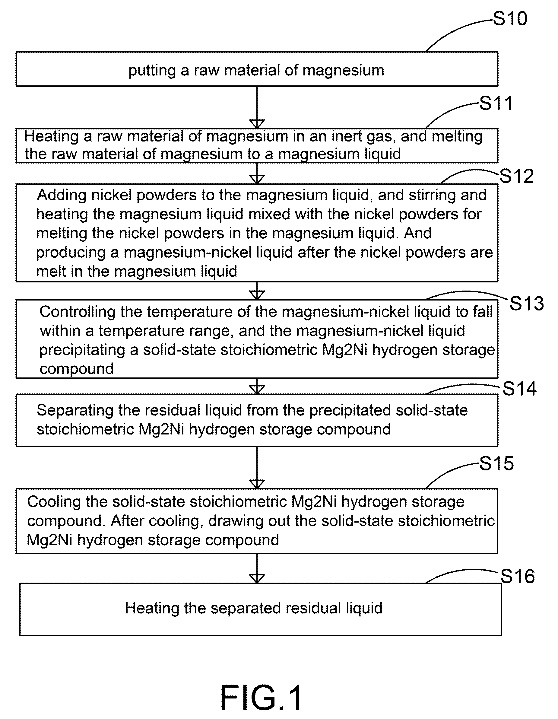
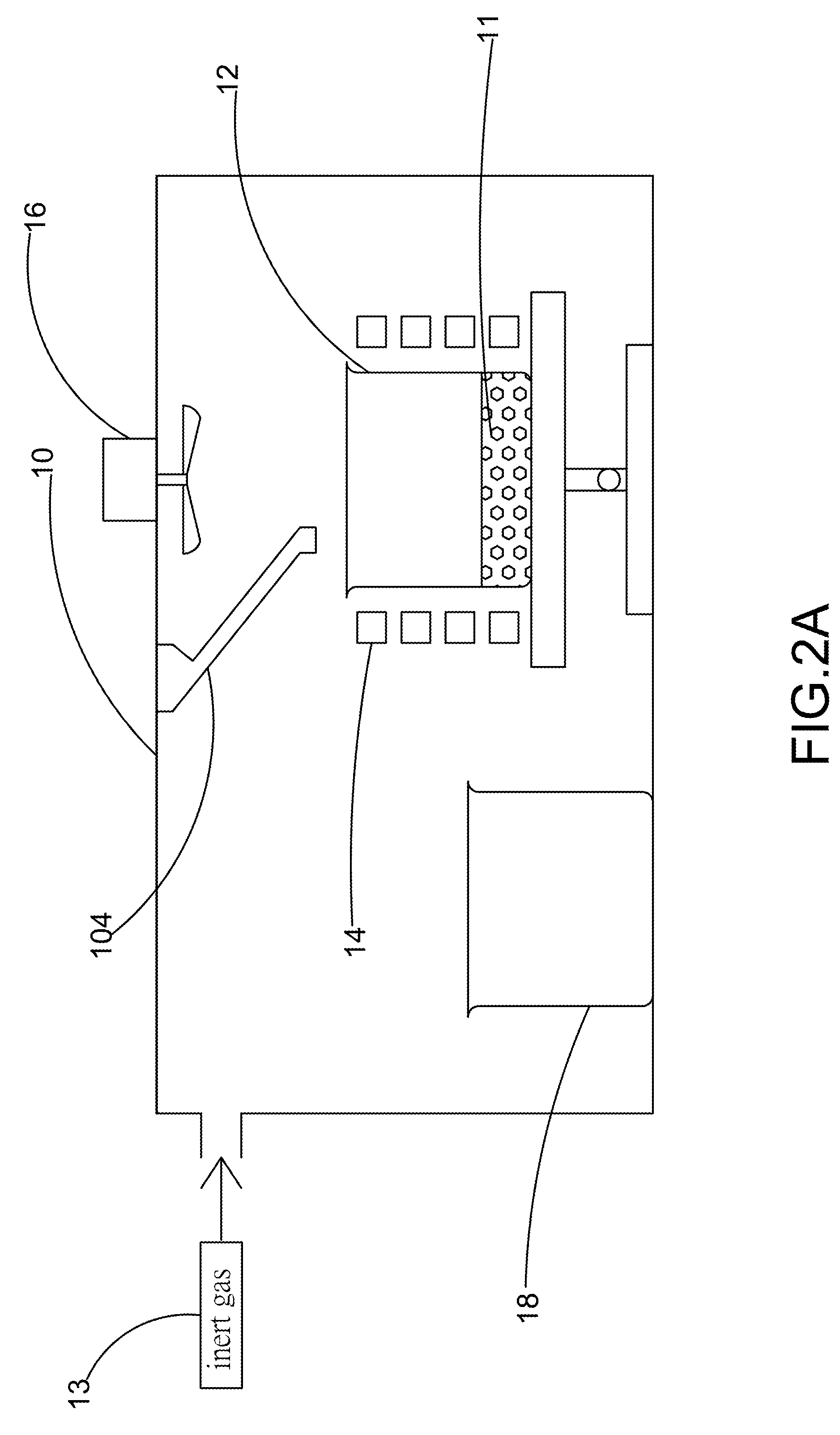
[0021]FIG. 1 and FIG. 2A show a flowchart and a schematic diagram of the apparatus in the steps S10 and S11 according to a preferred embodiment of the present invention. As shown in the figure, the present invention provides a method and apparatus for manufacturing stoichiometric Mg2Ni hydrogen storage compound. The apparatus comprises a vacuum chamber 10 with a material feeding tube 104, a first crucible 12, a heating device 14, a stirring device 16, and a second crucible 18. By using the apparatus, the step S10 is executed for putting a raw material of magnesium 11 into the first crucible 12, where the raw material of magnesium 11 is a magnesium metal bulk, and the material of the first crucible 12 is a...


PUM

PropertyMeasurementUnit
Temperatureaaaaaaaaaa
Ratioaaaaaaaaaa
Melting pointaaaaaaaaaa

Abstract

The present invention provides an apparatus for manufacturing stoichiometric Mg2Ni compound applicable to industry and capable of manufacturing continuously. The apparatus mainly comprises: a vacuum chamber, comprising a material feeding tube; a first crucible, set in the vacuum chamber; a heating device, set on the first crucible; a stirring device, set in the vacuum chamber, and above the first crucible; and a second crucible, set in the vacuum chamber, and on one side of the first crucible. The present invention also discloses a method to manufacture stoichiometric γ-phase Mg2Ni hydrogen storage compound. Through this apparatus and method, the residual waste magnesium-rich liquid in the crucible is poured to another independent crucible, and switch with the position of the crucible originally containing the γ-phase Mg2Ni hydrogen storage compound. Then, new raw materials of magnesium and nickel are added and heated. Repeat the smelt steps described above continuously, and a continuous manufacturing method is introduced. After the original crucible is cooled, the solid substances at the bottom of the crucible can be tapped down without further special treatments. Then stoichiometric γ-phase Mg2Ni hydrogen storage compound with an exactly atomic ratio of 2:1, without other phases, and with excellent hydrogen absorption-desorption dynamics is given.

Description

FIELD OF THE INVENTION[0001]The present invention relates generally to a hydrogen storage technology for new energies, and particularly to a method and apparatus for manufacturing stoichiometric Mg2Ni hydrogen storage compound.BACKGROUND OF THE INVENTION[0002]Owing to substantial growth of usage in fossil energy while which energy is drying up gradually, to pernicious substances harmful to human bodies produced by extensive application of fossil energy, such as SO2, CO, NOx, and to global climate changes caused by the greenhouse effect due to considerable quantity of exhausted CO2, the world is devoted to the development of new energy technologies. In particular, hydrogen energy is planned to be one of the major energies in the future by the International Energy Agency (IEA), because the byproduct thereof is water only, without CO2, which completely prevents pollution and the greenhouse effect. However, in practical applications, due to the light molecular weight of hydrogen, the st...

Claims


Application Information

Patent Timeline
IPC IPC(8): C22C1/02
CPCC01B3/0042Y02E60/327C22C23/00C22C1/02Y02E60/32
Inventor WU, YUAN-PANGBOR, HUI-YUNYANG, CHENGLIU, MING HAN
Owner NAT CHUNG SHAN INST SCI & TECH
Why Eureka
Try Eureka