Device and method for taking over flexible, flat objects

a flat object and device technology, applied in the direction of article feeders, pile separation, article delivery, etc., can solve the problems of less space and time available for actual transfer, more and more complex products are put together of several part-products and processed, etc., to achieve large acceleration and greater feed speed

Inactive Publication Date: 2010-09-16
FERAG AG
View PDF7 Cites 3 Cited by
  • Summary
  • Abstract
  • Description
  • Claims
  • Application Information

AI Technical Summary

Benefits of technology

[0031]The invention has particular advantages with the transfer of objects from a stationary conveyor belt to receiver compartments, which are conveyed past the transfer location. As a rule, the objects lie individually behind one another on the conveyor belt. For this reason, with a given processing rate, 3-4 times greater feed speeds are necessary than with a more compact formation in the feed, e.g. with objects conveyed in a hanging manner by way of grippers. Moreover, the time widow, in which the opening of the receiver compartment runs past the stationary feed location and in which the transfer may therefore take place, is significantly smaller that in the case of a transfer from grippers which may be co-moved with the receiver compartments. The latter also necessitates large accelerations whose effects are advantageously alleviated by way of the invention.

Problems solved by technology

Moreover, more and more complex products are put together of several part-products and processed.
For this reason, little space and time is available for the actual transfer.

Method used


Image

  • Device and method for taking over flexible, flat objects
  • Device and method for taking over flexible, flat objects
  • Device and method for taking over flexible, flat objects

Examples


Embodiment Construction

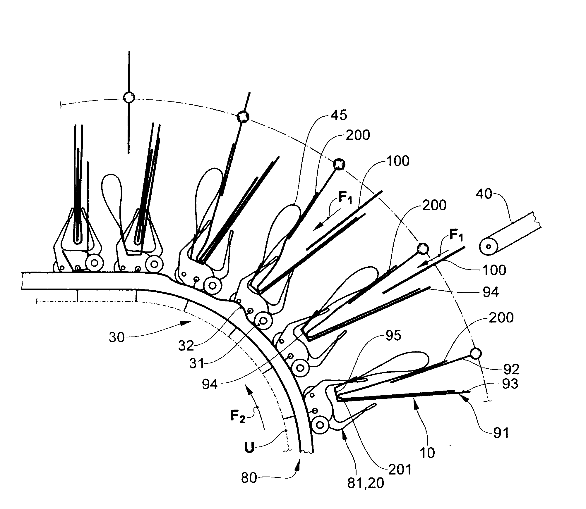
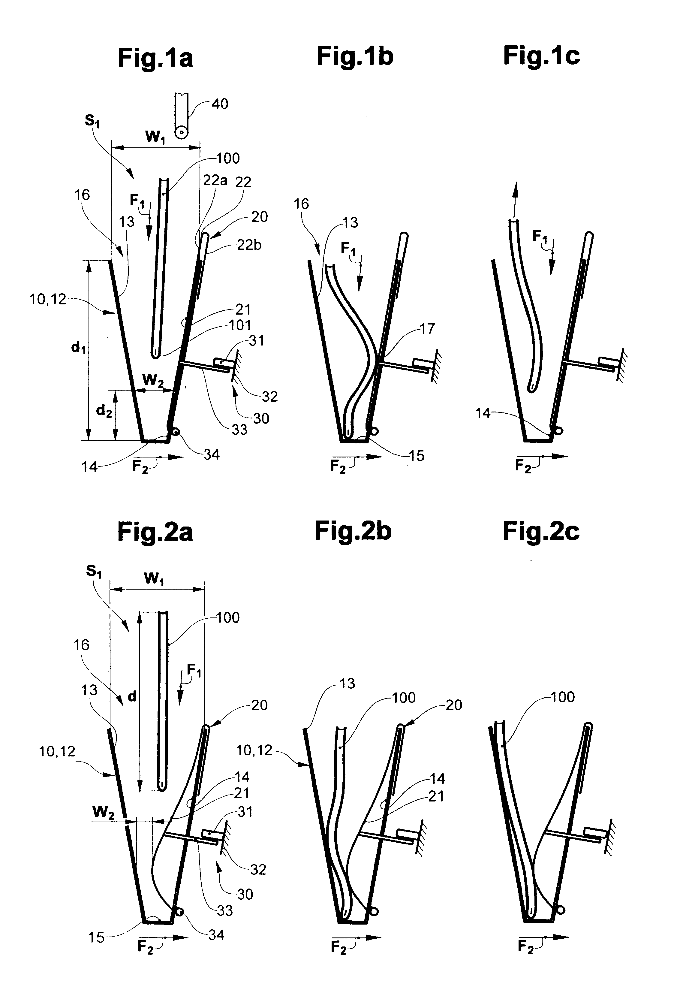
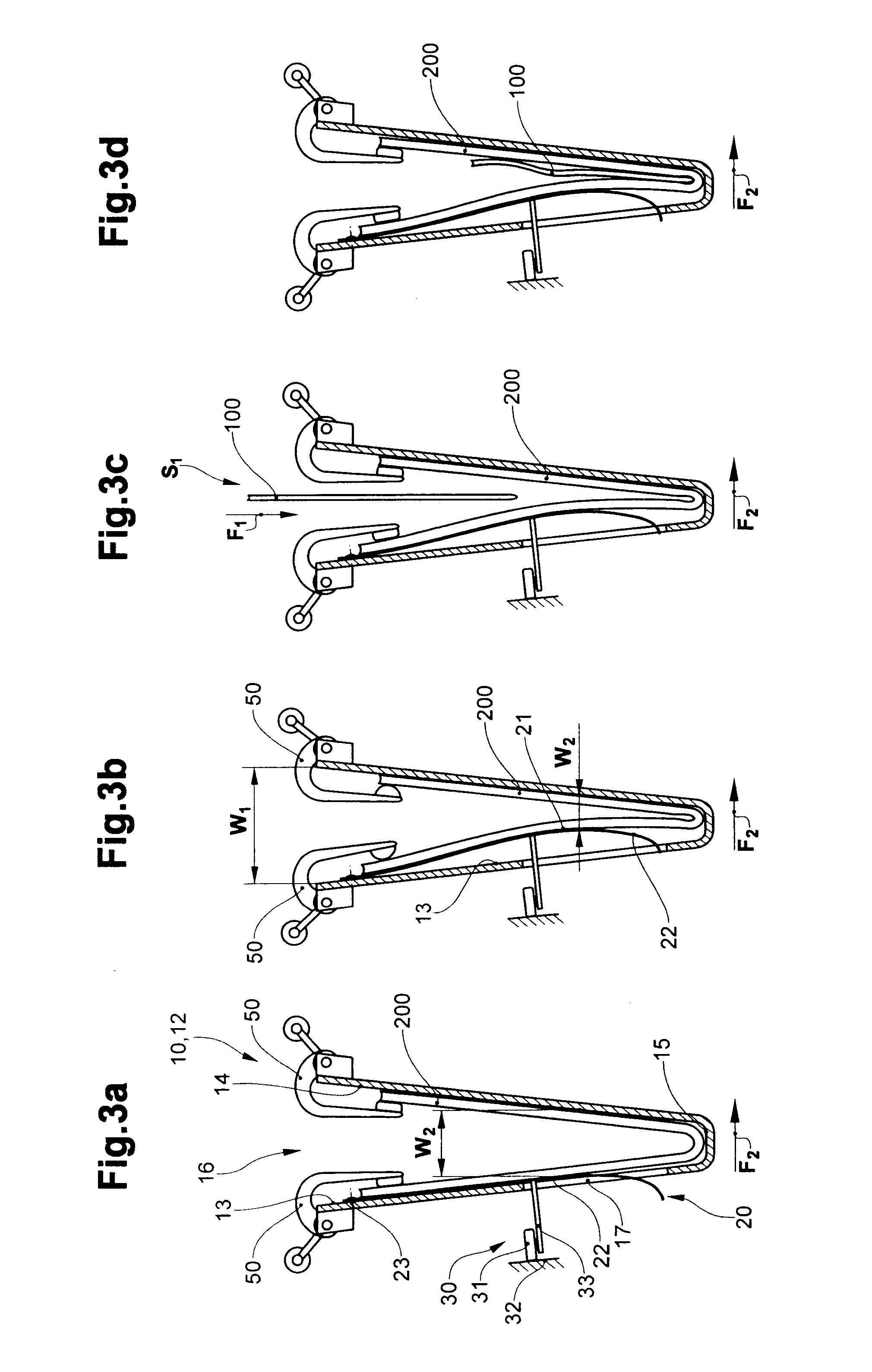
[0038]FIGS. 1a-c and 2a-c show a receiver unit 10 in the form of a pocket 12 at various points in time on feeding an object 100 in a feed direction F1 to a take-over location S1. The pocket 12 passes the take-over location S1 in a conveyor direction F2, which here is perpendicular to the feed direction F1. The pocket 12 comprises two plane, lateral support surfaces 12, 14, a pocket base acting as an abutment 15 and an entry opening 16. The pocket 12, moreover, comprises a controllable narrowing element 20 with an active surface 21. The narrowing element 20 is located in the inactive condition with FIG. 1a-c, in which its active surface 21 runs in the direct vicinity parallel to one of the support surfaces 14. With FIGS. 2a-c, the narrowing element 20 is in the active condition, i.e. is regionally lifted from the support surface 14 to the inside of the pocket or to the other support surface 13.

[0039]The pocket 12 has an opening width W1 in the region of the entry opening 16, which is...


PUM

PropertyMeasurementUnit
flexibleaaaaaaaaaa
widthaaaaaaaaaa
distanceaaaaaaaaaa

Abstract

A device and a method for taking over flexible, two-dimensional objects (100), in particular printed products, at a take-over location (S1). The objects (100) are received by receiver units (10, 12). Controllable narrowing elements (20) are present, in order to prevent a squashing and rebounding of the objects (100) on or from an abutment of the receiver unit (10, 12), with which narrowing elements, in an active condition, the opening width (W2) of the receiver unit (10, 12) in a middle region between an entry opening (16) of the receiver unit (10, 12) and the abutment (15), may be reduced compared to an inactive condition. These are controlled with a control device (30). A more reliable positioning of the objects (100) in the receiver unit (10, 12), in particular at high feed speeds and with thin, elastically deformable objects (100), may be achieved.

Description

BACKGROUND OF THE INVENTION[0001]1. Field of the Invention[0002]The invention lies in the field of conveying and further processing flexible, two-dimensional objects, in particular printed products. It relates to a device and to a method for taking over such objects, in particular printed products such as e.g. newspapers, magazines, brochures, catalogues, part-products of such printed products, or supplements, advertising material, cards, goods samples, CDs.[0003]2. Description of Related Art[0004]The further processing of printed products is carried out at ever increasing speeds. Moreover, more and more complex products are put together of several part-products and processed. Both of these, the high speeds and the complexity of the products, require a very accurate control of the product position at each point in time of the processing.[0005]A process which occurs very often is the so-called insertion: one or more part-products (also called pre-products) are inserted into a folded ...

Claims


Application Information

Patent Timeline
Patent Type & Authority Applications(United States)
IPC IPC(8): B65H39/00
CPCB65H29/003B65H29/26B65H2511/22B65H2511/17B65H2405/352B65H2405/22B65H2301/4476B65H2301/432B65H39/02B65H29/68B65H2220/01B65H2220/02B65H2220/11
Inventor STAUBER, ERWIN
Owner FERAG AG
Why Eureka
Try Eureka