Ac motor drive control device and method

a technology of drive control and ac motor, which is applied in the direction of motor/generator/converter stopper, electronic commutator, dynamo-electric converter control, etc., can solve the problems of sudden reduction of torque command value and unstable control, and achieve the effect of stable drive control of an ac motor

Active Publication Date: 2010-09-16
DENSO CORP
View PDF4 Cites 31 Cited by
  • Summary
  • Abstract
  • Description
  • Claims
  • Application Information

AI Technical Summary

Problems solved by technology

However, in cases in which the low-pass filter processing is performed, an undesirable situation is caused at a point when the torque command value is suddenly reduced.
This type of delay in the switching of control modes generates undesirable hunting (vibrations) or the like in the current phases, possibly resulting in unstable control.

Method used


Image

  • Ac motor drive control device and method
  • Ac motor drive control device and method
  • Ac motor drive control device and method

Examples


modified embodiment

[0042]In the above-described embodiment, the control mode judgment unit 108 receives torque command value T* from the current command calculator 110, and calculates power P in accordance with the torque command value T*. In contrast, in the modified embodiment described below, a drive control device 101 that can control an AC motor without using torque command value T* is illustrated.

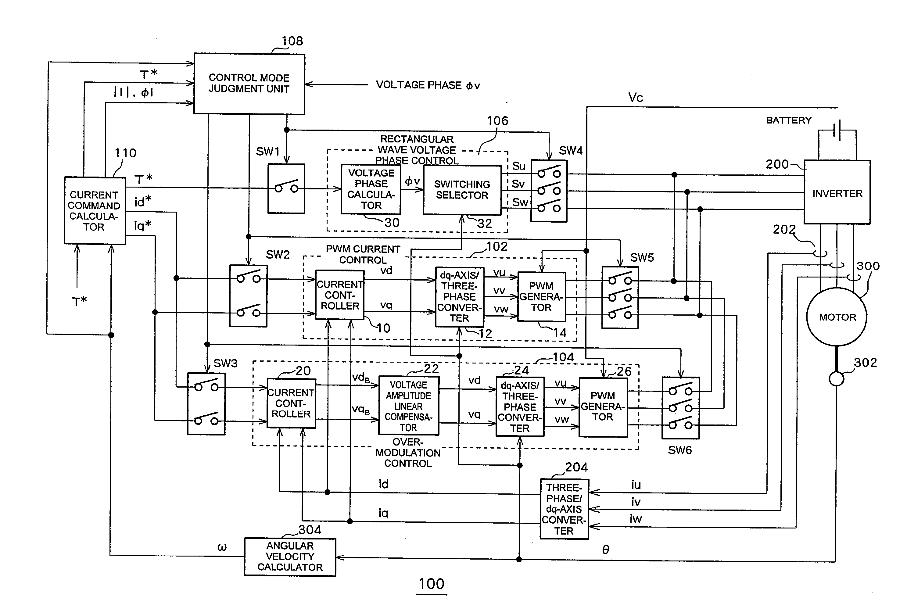
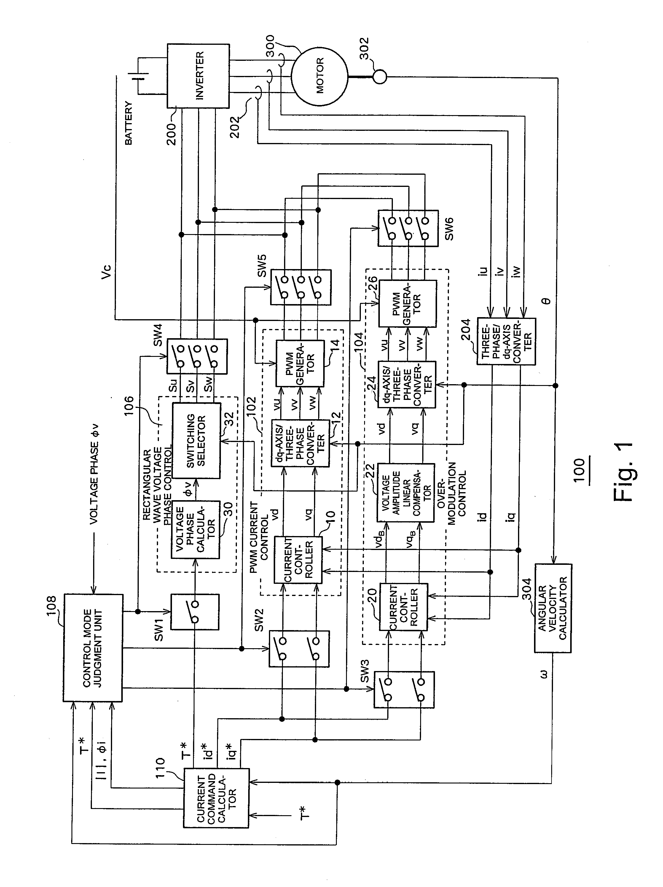
[0043]The drive control device 101 is configured as shown in FIG. 10 including PWM current control unit 102, overmodulation control unit 104, rectangular wave voltage phase control unit 106, control mode judgment unit 109, and current command calculator 111. Similarly to in the above-described embodiment, the drive control device 101 is connected to an AC motor 300 via an inverter 200, and controls drive of the AC motor 300 by supplying three-phase electric power to the inverter 200 from one of the PWM current control unit 102, the overmodulation control unit 104, or the rectangular wave voltage phase c...


PUM


Abstract

An AC motor drive control device includes a control mode judgment unit that performs a judgment based on required voltage amplitude required by a synchronous AC motor, in order to switch units for applying voltage to the AC motor to one of a rectangular wave voltage phase control unit, an overmodulation control unit, and a PWM current control unit.

Description

TECHNICAL FIELD[0001]The present invention relates to a drive control device and method that enable further stabilized control of an alternating-current (AC) motor.BACKGROUND ART[0002]In order to drive an AC motor by means of a direct-current power source, a drive method using an inverter is commonly employed. Typically, the inverter is subjected to switching control by an inverter drive circuit, and, for example, a pulse width modulation (PWM) waveform voltage is applied to the AC motor.[0003]There has been known a method for supplying power to an AC motor by selectively switching, by means of switches, among PWM current control, mode, overmodulation control mode, and rectangular wave voltage phase control mode. When the voltage amplitude exceeds the peak value of a reference triangle wave, the control mode is switched from the PWM current control mode to the overmodulation control mode. Further, when the voltage amplitude exceeds a value obtained by multiplying the peak value of t...

Claims


Application Information

Patent Timeline
Patent Type & Authority Applications(United States)
IPC IPC(8): H02P6/10H02P6/08H02P6/06H02P6/17H02P6/28
CPCH02M7/53875H02P21/0089H02M2007/53876H02M7/53876
Inventor OHTANI, HIROKINAKAMURA, MAKOTOYAMADA, KENJIOKAMURA, MASAKIHANADA, HIDETO
Owner DENSO CORP
Why Eureka
Try Eureka