Structure

a technology of structure and base, applied in the field of structures, can solve the problems of requiring a very wide base and a rusto-conical structure, and achieve the effects of reducing the rcs of the structure, and preferably minimizing the rcs

Inactive Publication Date: 2010-09-16
BAE SYSTEMS PLC
View PDF34 Cites 16 Cited by
  • Summary
  • Abstract
  • Description
  • Claims
  • Application Information

AI Technical Summary

Benefits of technology

[0006]The inventors in the present case have realised that the RCS of a structure can be significantly reduced, in particular for a structure comprising a tower, by arranging for at least a portion of the outer surface of the tower to be inclined at a predetermined angle relative to the vertical. The angle of inclination is calculated to reduce the RCS of the tower over one or more selected frequency bands, providing a reduced RCS in each of the one or more frequency ranges whether or not the RCS is actually minimized in any one range.
[0009]Whereas it is known to provide structures in the form of towers made using at least one frusto-conical section, such structures are designed primarily for their aerodynamic and load-bearing properties, not in order to minimize their RCS. According to the present invention, with careful selection of the shape of a structure, in particular of the angle of inclination of the surface of the structure, the RCS of that structure may be reduced and preferably minimized.
[0010]A structure such as a tower comprising cylindrical and / or frusto-conical sections, and hence having a circular cross-section, is likely to have a substantially uniform RCS over a range of azimuthal angles, that is, the RCS will not have been minimized in respect of any one direction. However, if it is known that the RCS of the structure needs to be minimized in only one direction, for example because the structure is likely to be in the field of view of a single radar installation at a single known location, cross-sections other than circular may be used, subject to aerodynamic and other considerations, to further reduce the RCS of the structure in that one direction.
[0012]Typical shaping angles vary according to the height of the tower and the relative geometries of the frustum and any other section, such as a cylindrical section (if required). Substantial reductions in monostatic RCS, preferably in the range of 10-20 dBsm, are achievable in a tower comprising a frusto-conical section, for example, using slope angles of less than 2° for most tower geometries at the frequencies of interest. Preferably, an angle is selected which gives good reductions in more than one frequency band in order to minimize the impact of the structure on the most widely deployed radar installations.

Problems solved by technology

However, a very tall frusto-conical structure may in practice require a very wide base.

Method used


Image

  • Structure
  • Structure
  • Structure

Examples


Embodiment Construction

[0022]Preferred embodiments of the present invention will now be described in more detail, by way of example only, with reference to the accompanying drawings.

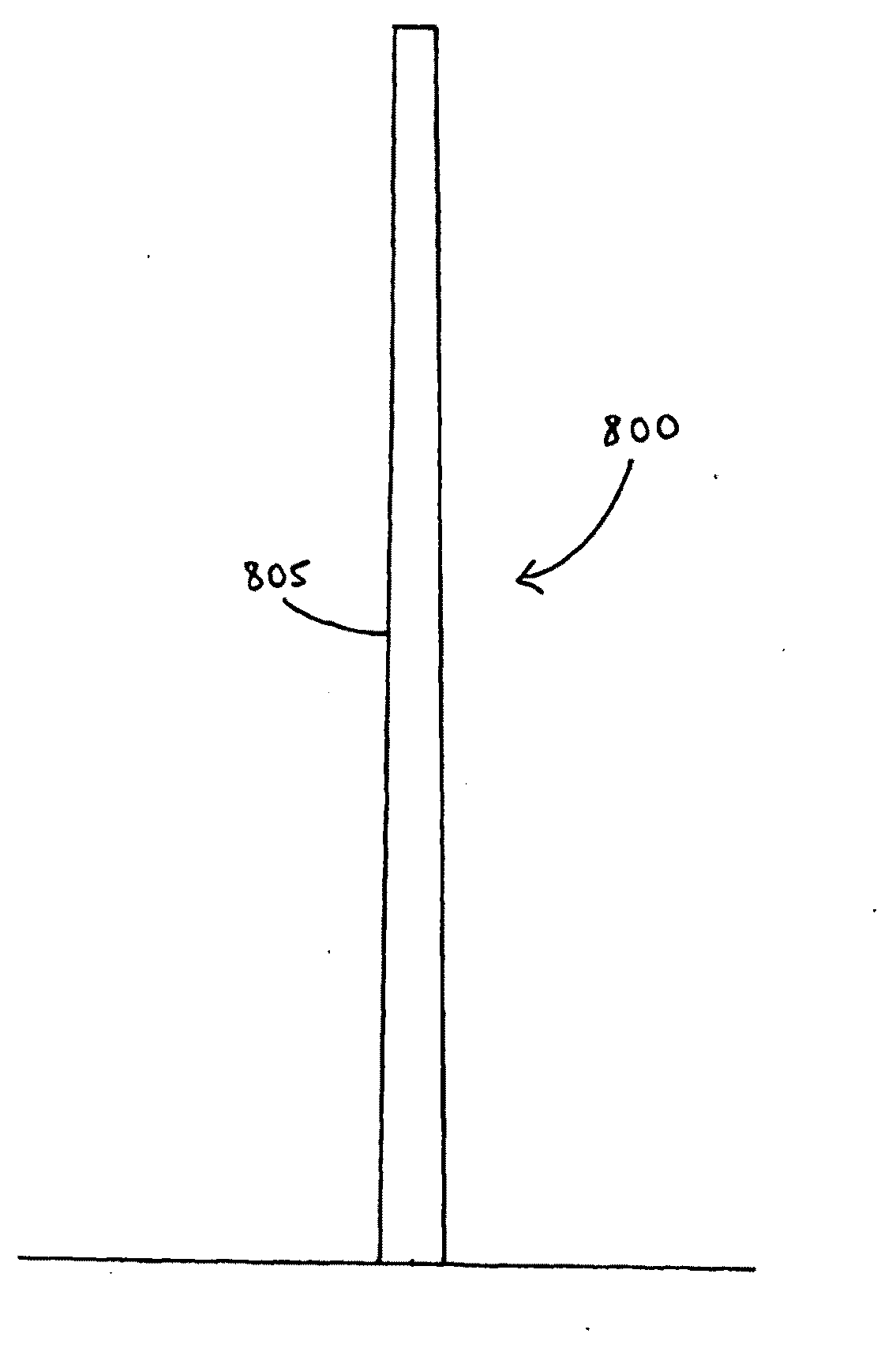
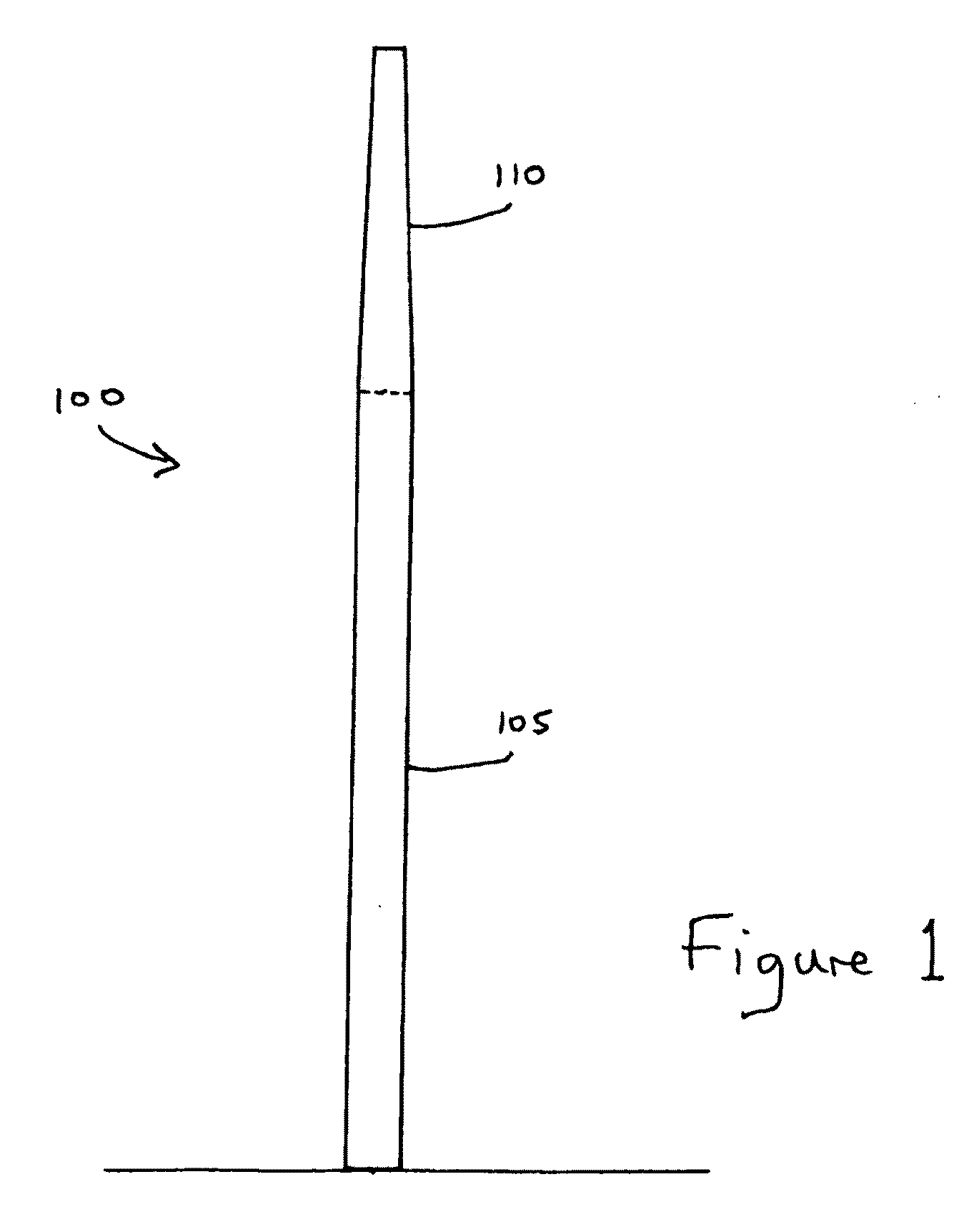
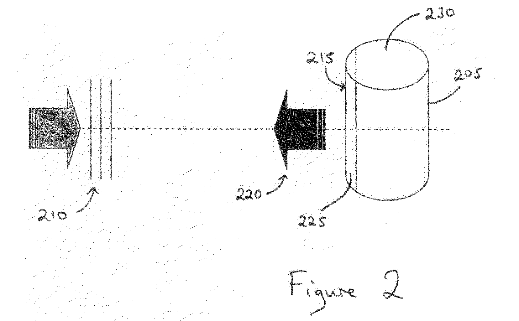
[0023]A preferred embodiment of the present invention will now be described in the context of a wind turbine. Wind turbines are often deployed in open and exposed locations such as coastal or mountainous areas, and in large numbers forming so-called wind farms. Such locations are often likely to be within the field of coverage of coastal radar or air traffic control radar installations.

[0024]A wind turbine, for example one manufactured by Vestas Technology™, is a large structure comprising a tower, a nacelle to house a generator, and a two or three-blade rotor. The tower itself is approximately 80 metres tall. The inventors in the present case have modelled the electromagnetic properties of one of the wind turbines of Vestas Technology™, the V82 turbine, using a BAE SYSTEMS plc proprietary physical optics computer program call...


PUM


Abstract

A structure, and a method for modifying the design of a structure, are provided such that the structure includes features designed to reduce and preferably minimize the radar cross-section of the structure over one or more predetermined frequency ranges. A structure is provided having an inclined surface, wherein the angle of inclination is selected for which the level of radar cross section is below a local maximum in the sidelobes in each of the scattering patterns of incident electromagnetic radiation at frequencies within one or more predetermined frequency ranges. In the particular case of a tower, for example of a wind turbine, the radar cross-section of the tower may be minimized for two or more radar bands by appropriate selection of the angle of inclination of a frusto-conical portion of the tower. Ideally, the tower is constructed entirely in the form of a cone frustum.

Description

RELATED APPLICATION INFORMATION[0001]This application is a United States National Phase Patent Application of, and claims the benefit of, International Patent Application No. PCT / GB2007 / 003448 which was filed on Sep. 13, 2007, and which claims priority to British Patent Application No. 0618696.9587.1, which was filed on Sep. 22, 2006, and which claims priority to European Patent Application No. 06279986.9, which was filed on Sep. 22, 2006, the disclosures of all of which are incorporated herein by reference.FIELD OF THE INVENTION[0002]This invention relates to structures which conventionally have large radar signatures and in particular, but not exclusively, to improved structures having structural features that serve to reduce their radar cross-section (RCS).BACKGROUND INFORMATION[0003]Currently, approximately 47% of planning applications for wind farms in the United Kingdom are objected to on the basis of their potential to cause interference to radar signals. Consequently, a numb...

Claims


Application Information

Patent Timeline
Patent Type & Authority Applications(United States)
IPC IPC(8): H01Q17/00E04H12/00
CPCF05B2260/99H01Q19/023
Inventor PINTO, JONATHANMATTHEWS, JAMES CHRISTOPHER GORDON
Owner BAE SYSTEMS PLC
Why Eureka
Try Eureka