
High bandwidth, efficient graphics hardware architecture

a graphics hardware and high bandwidth technology, applied in static indicating devices, cathode-ray tube indicators, instruments, etc., can solve the problems of limiting the performance per watt of graphics applications, large gpus of mainstream, and high cost, and achieve the effect of high bandwidth

Inactive Publication Date: 2010-09-16
DIGITALPTICS CORP INT
View PDF3 Cites 19 Cited by
  • Summary
  • Abstract
  • Description
  • Claims
  • Application Information

AI Technical Summary

Benefits of technology

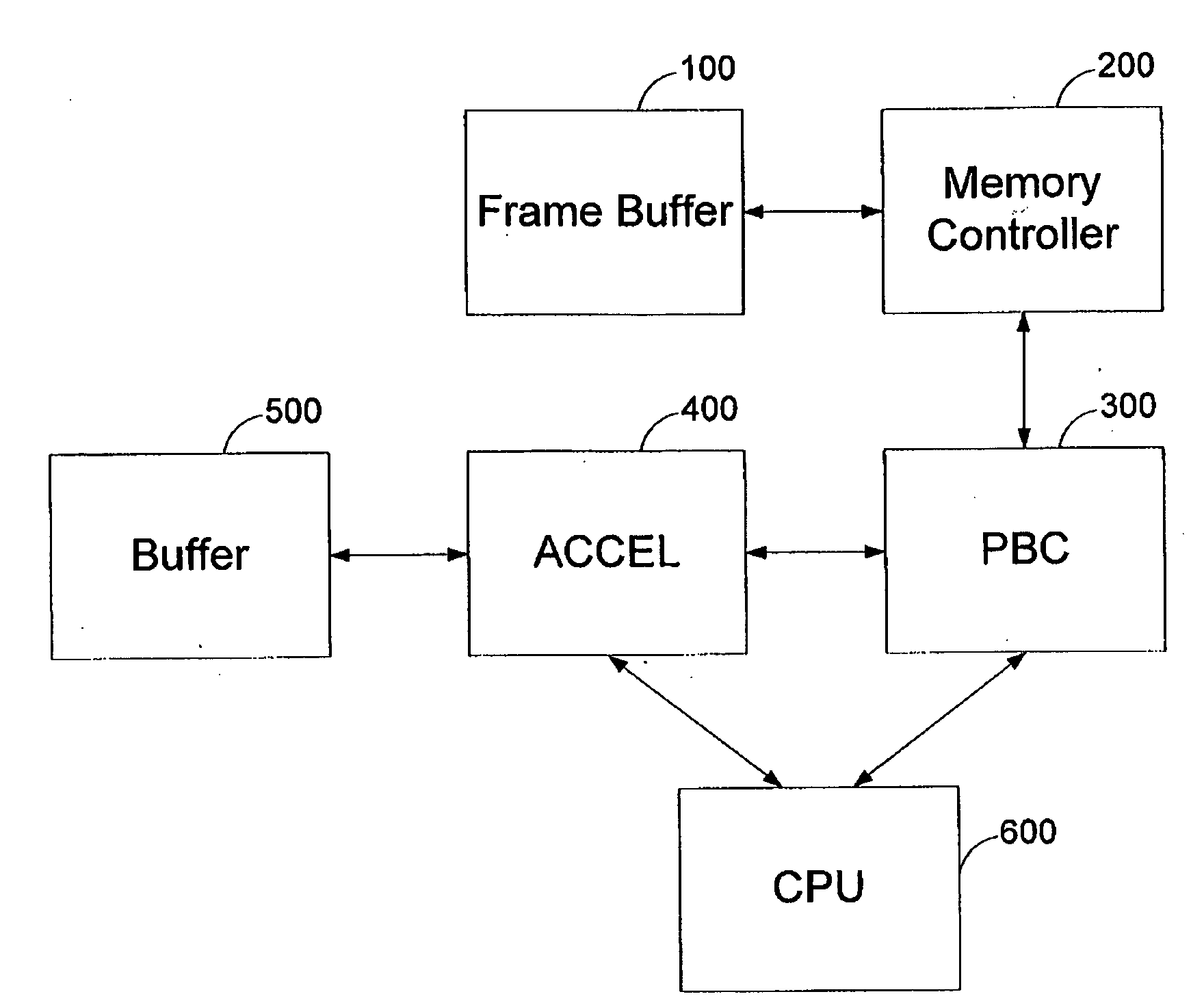
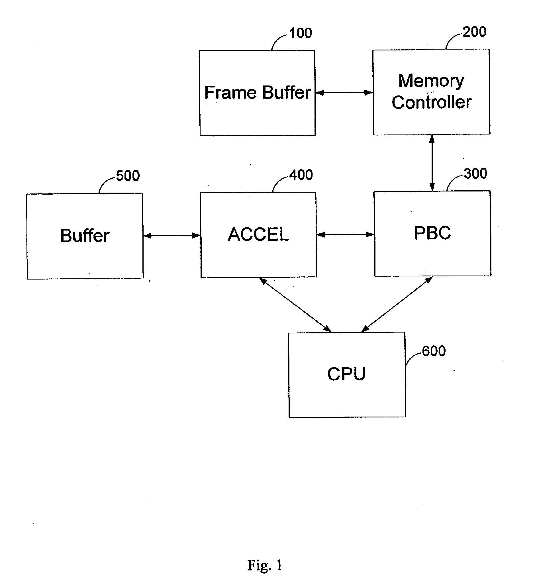
[0017]The present invention relates to a system according to claim 1, where the pixel buffer cache comprises at least one row descriptor for tracking and monitoring the activities of read and write requests of a particular tile. A system for providing a high bandwidth memory access to a graphics processor comprising: (a) a frame buffer for storing at least one frame, where said frame is stored in a tiled manner; (b) a memory controller for controlling said frame buffer; (c) a pixel buffer cache for storing multiple sections of at least one memory row of said frame buffer, and for processing requests to access pixels of said frame buffer; (d) a graphics accelerator having an interface to said pixel buffer cache for processing a group of related pixels; and (e) a CPU for processing graphic commands and controlling said graphics accelerator and said pixel buffer cache.

Problems solved by technology

On the one hand, mainstream GPUs are usually large, expensive, and require a tremendous amount of power to operate (which also makes cooling a concern), and on the other hand, low-end and mobile GPUs are substantially limited and are intended for small resolution screens.
Memory bandwidth is the predominant performance per Watt limiting factor in graphics applications, due to the constantly increasing resolutions and frame rates.
However, cache memory is often expensive, and typically its cost rises as its required speed and size increase.
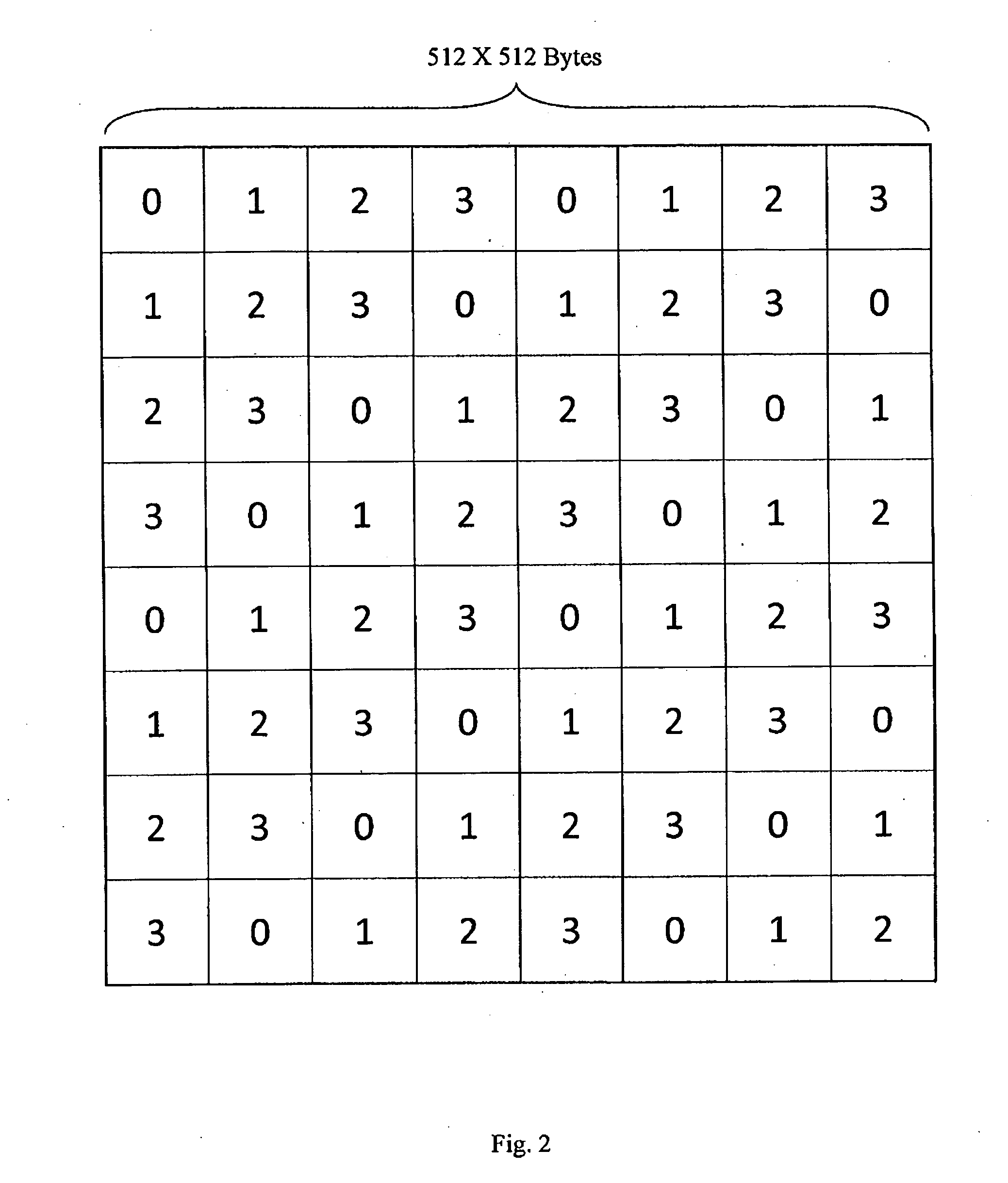
Nevertheless, the described memory is not arranged in a full two dimensional tile configuration method which increases memory access speed of graphics operations.

Method used


Image

  • High bandwidth, efficient graphics hardware architecture
  • High bandwidth, efficient graphics hardware architecture
  • High bandwidth, efficient graphics hardware architecture

Examples


Embodiment Construction

Terms Definitions

[0034]For the sake of brevity the following terms are defined explicitly:

[0035]Pixel—a picture element, which is the smallest item of information in a frame. Pixels are normally arranged in a 2-dimensional grid. The terms pixel and pixel values are used interchangeably. In the following description a pixel consists of 4 bytes of information: Red, Green, Blue, and Alpha.

[0036]Bank—a memory module for storing data including pixel values. For the following description a single data interface is assumed for all the memory banks.

[0037]Burst—a burst is the smallest address accessible data portion in the memory, i.e. in an “atomic” manner. In the following description a burst stores 8 adjacent horizontal pixels.

[0038]Row—a logical quantity of data within the bank, having an accessible address, for storing a number of adjoining bursts. The adjoining bursts of a row may be accessed without additional access memory module penalty. Rows in parallel banks can be activated and p...


PUM


Abstract

The present invention relates to a system according to claim 1, where the pixel buffer cache comprises at least one row descriptor for tracking and monitoring the activities of read and write requests of a particular tile. A system for providing a high bandwidth memory access to a graphics processor comprising: (a) a frame buffer for storing at least one frame, where said frame is stored in a tiled manner; (b) a memory controller for controlling said frame buffer; (c) a pixel buffer cache for storing multiple sections of at least one memory row of said frame buffer, and for processing requests to access pixels of said frame buffer; (d) a graphics accelerator having an interface to said pixel buffer cache for processing a group of related pixels; and (e) a CPU for processing graphic commands and controlling said graphics accelerator and said pixel buffer cache.

Description

FIELD OF THE INVENTION[0001]The present invention relates to the field of graphics processing hardware architectures. More particularly, the invention relates to a method and system for providing a graphics processor with a high bandwidth access to a memory shared by other processors.BACKGROUND OF THE INVENTION[0002]The field of Digital TV (DTV) applications has generated a great deal of interest from consumers and providers for the past two decades. Many households have adopted a digital cable or satellite Set-Top Box (STB) for streaming encoded video and other multimedia contents. As the technology of digital STBs and media players develops, the requirement for a more engrossing user experience is also expanding. Today's broadcasting and recording standards provide advanced studio-quality image composition, 3D graphics, complex and dynamic menus and subtitles, as apposed to previous TV broadcast contents which provided a simple menu system and basic subtitles.[0003]Initially, the ...

Claims


Application Information

Patent Timeline
Patent Type & Authority Applications(United States)
IPC IPC(8): G09G5/36
CPCG09G5/393G09G5/395G09G2360/125G09G2360/122G09G2360/121
Inventor KAUFMAN, SHACHAR CHAIMOXMAN, GEDALIADARSHAN, NIR
Owner DIGITALPTICS CORP INT
Learn More