Lighting device for display device, display device, and television receiver

Inactive Publication Date: 2010-09-16
SHARP KK
View PDF11 Cites 14 Cited by
  • Summary
  • Abstract
  • Description
  • Claims
  • Application Information

AI Technical Summary

Benefits of technology

[0013]Furthermore, the LED substrate is attached to the opposite surface of the chassis from the surface that faces the optical member. Therefore, the LED substrate is exposed to the outside.

Problems solved by technology

According to this configuration, when LEDs or their peripheral components (a lead frame, wires, etc.)

Method used


Image

  • Lighting device for display device, display device, and television receiver
  • Lighting device for display device, display device, and television receiver
  • Lighting device for display device, display device, and television receiver

Examples


Example

[0026]A first embodiment in accordance with the present invention will be explained with reference to FIGS. 1 through 6. In this embodiment, a liquid crystal display device 10 will be illustrated as a display device.

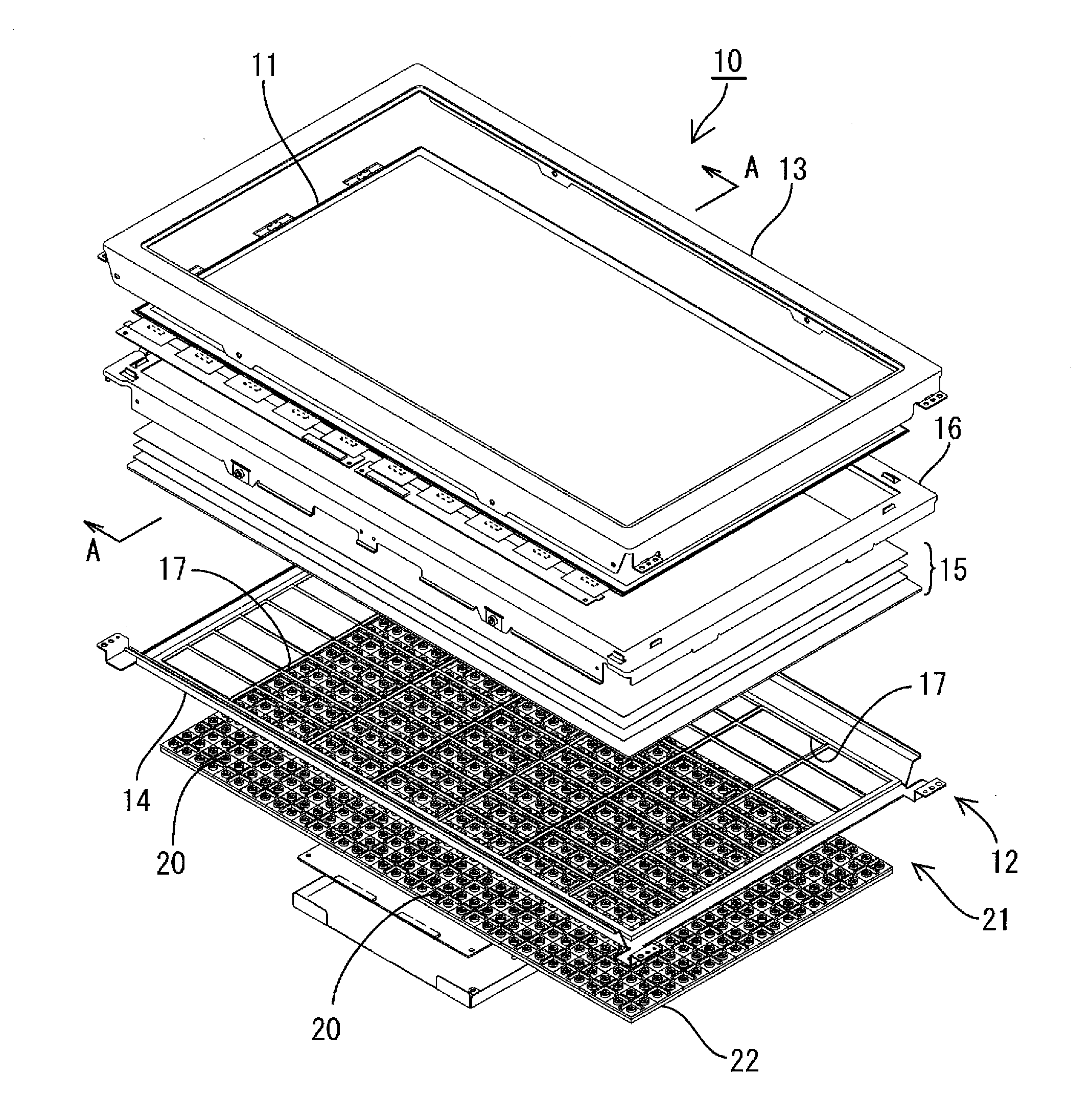
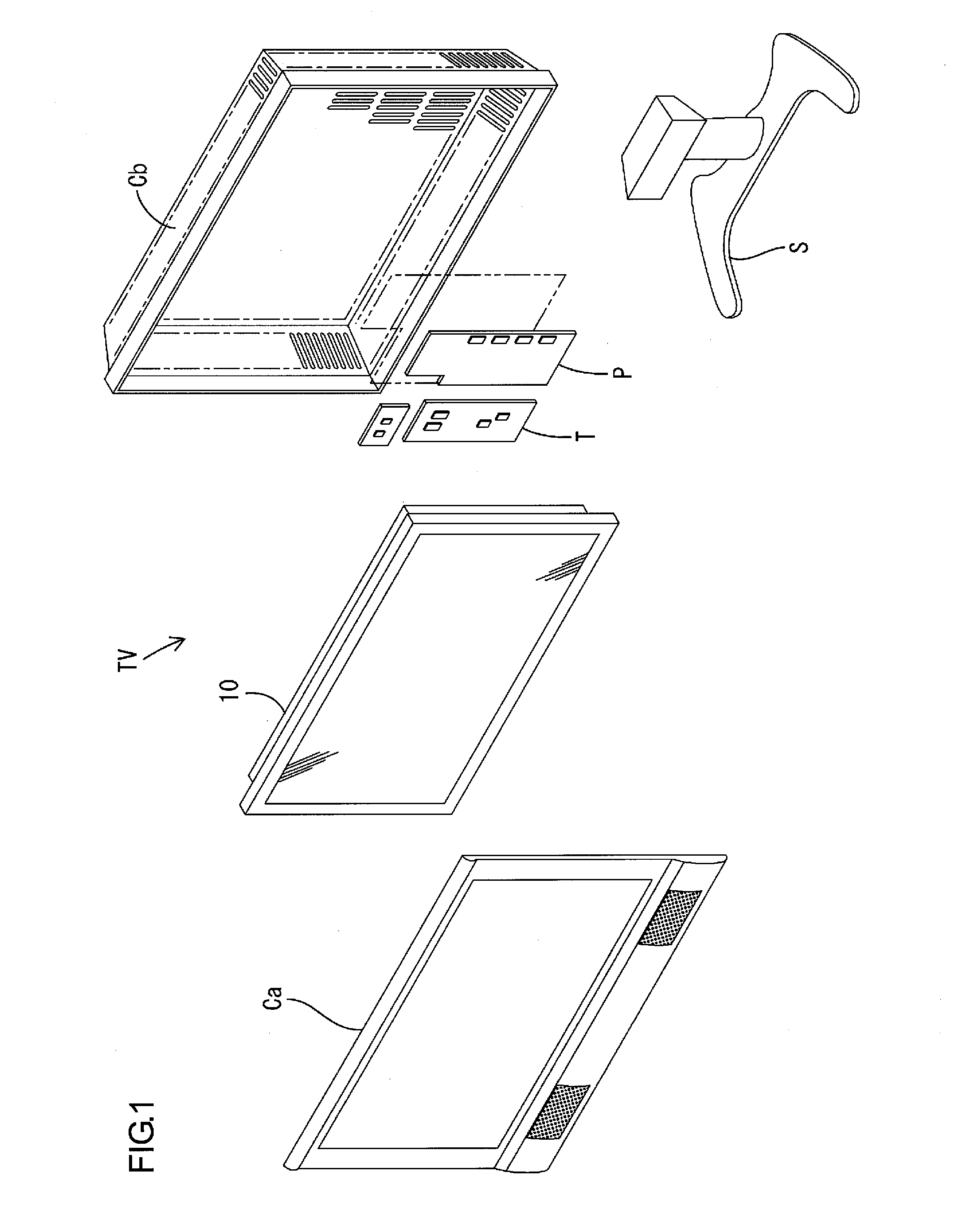
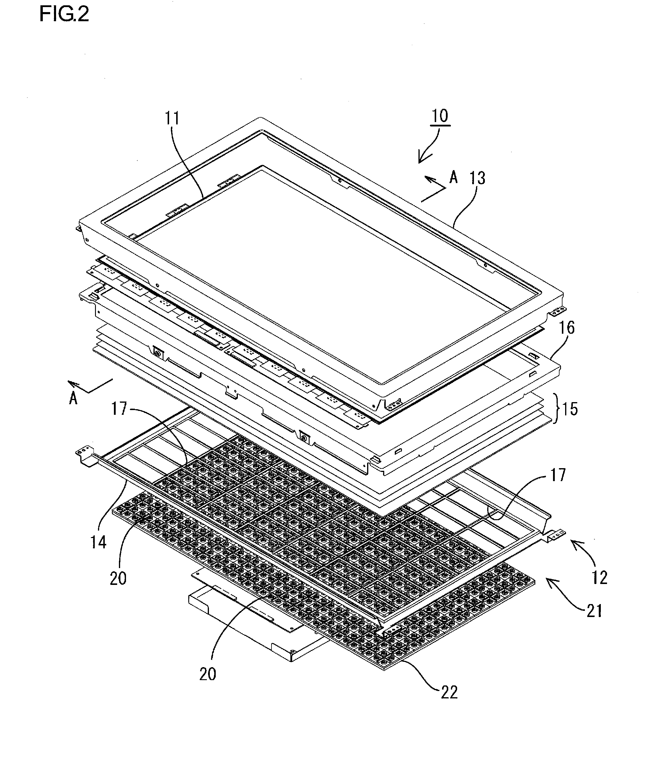
[0027]FIG. 1 is an exploded perspective view illustrating a schematic configuration of a television receiver of this embodiment; FIG. 2 is an exploded perspective view illustrating a schematic configuration of a liquid crystal display device that the television receiver of FIG. 1 includes; FIG. 3 is a sectional view along line A-A of the liquid crystal display device of FIG. 2; FIG. 4 is a perspective view illustrating a schematic configuration of an LED substrate that a backlight device includes; FIG. 5 is an enlarged sectional view of a main part of the backlight device; and FIG. 6 is an explanatory view illustrating an operational effect that the backlight device produces.

[0028]The television receiver TV of this embodiment is, as illustrated in FIG. 1, is configured b...

Example

Second Embodiment

[0052]Next, a second embodiment in accordance with the present invention will be explained with reference to FIGS. 7 and 8. The difference from the above-explained first embodiment is in that the LED substrates alone are provided with the reflectors that are a light reflection mechanism. Other aspects are similar to the above-explained embodiment. Portions identical with the above-explained embodiment will be designated with the identical reference characters, while repetitive explanations will be omitted.

[0053]FIG. 7 is a perspective view illustrating a schematic configuration of an LED substrate that is attached to a backlight device of this embodiment. FIG. 8 is an enlarged sectional view of a main part of the backlight device.

[0054]As illustrated in FIG. 7, each LED substrate40 has a configuration of a face having the LED light sources 20 arranged thereon. Specifically, five (in the long-side direction of the LED substrate 40) by two (in the short-side direction...

Example

Third Embodiment

[0064]Next, a third embodiment in accordance with the present invention will be explained with reference to FIG. 9. The difference from the above-explained embodiments 1, 2 is in the aspect of attaching the LED substrates to the chassis. The other aspects are similar to the above-explained embodiments. Portions identical with the above-explained embodiments will be designated with the identical reference characters, while repetitive explanations will be omitted.

[0065]FIG. 9 is an exploded perspective view illustrating a schematic configuration of the liquid crystal display device of this embodiment.

[0066]As illustrated in FIG. 9, LED substrates 60 are disposed in lines on a single backlight substrate 61 with the adjacent LED substrates 60 close to each other. It is configured so that drive of the LED substrates 60 can be individually controlled, and the LED substrates 60 can be individually removed from the backlight substrate 61.

[0067]Such a liquid crystal display d...


PUM


Abstract

A lighting device 12 for a display device comprising: a plurality of LED light sources 20, an LED substrate 21 having the plurality of LED light sources 20 mounted thereon, an optical member 15 arranged on a light emission side of the LED sources 20, and a chassis 14 for supporting the plurality of LED light sources 20. The chassis 14 has a cutout 17. The LED substrate 21 is attached to an opposite surface of the chassis 14 from a surface that faces the optical member 15 such that the LED light sources 20 are exposed toward the optical member 15 side through the cutout 17.

Description

TECHNICAL FIELD[0001]The present invention relates to a lighting device for a display device, a display device, and a television receiver.BACKGROUND ART[0002]For example, a liquid crystal panel used in a liquid crystal display device such as a liquid crystal television is not self-luminous. Because of this, a backlight device is necessary as an external light source that supplies illumination light to the liquid crystal panel. As the liquid crystal display device has been being upsized these days, improvement in the brightness and light uniformity of the backlight device has been required. In order to meet this requirement, a backlight device having an LED (light emitting diode) as the light source is receiving attention.[0003]By the way, the LEDs have a higher heat generation rate, and the backlight device including LED substrates having a large number of LEDs disposed in a two-dimensional array can be heated to a high-temperature state due to heat generation by the LEDs. In this c...

Claims


Application Information

Patent Timeline
IPC IPC(8): H04N5/44H01L33/48G02F1/13357
CPCG02F1/133603G02F2203/68G02F2001/133613G02F1/133608G02F1/133613
Inventor HISAKAWA, KOHJI
Owner SHARP KK
Why Eureka
Try Eureka