Surgical tether apparatus and methods of use

a technology of tethering device and tethering device, which is applied in the field of surgical tethering device and methods of use, can solve the problems of no longer providing any further benefit to constraint device, constraint device may last longer than traditional instrumentation, and may take several months to form, etc., to achieve the effect of reducing load and wear, and modulating load

Active Publication Date: 2010-09-16
SIMPIRICA SPINE
View PDF103 Cites 74 Cited by
  • Summary
  • Abstract
  • Description
  • Claims
  • Application Information

AI Technical Summary

Benefits of technology

[0011]The step of performing the spinal fusion procedure may comprise applying bone grafting material to at least one of posterior, lateral, posterolateral or interbody locations on the adjacent vertebrae. Bone graft may be placed between or alongside the spinous processes of the vertebrae to be fused, and to which the constraint is coupled. Sometimes performing the spinal fusion procedure may comprise intervertebral grafting in a disc space between the pair of adjacent vertebrae or applying bone grafting material to the superior spinous process and the inferior spinous process. Performing the spinal fusion procedure may also comprise implanting a first prosthesis into the patient. The first prosthesis may be engaged with at least a portion of the spinal segment. The constraint device may modulate loads borne by the first prosthesis or tissue adjacent thereto. The constraint device may be implanted and coupled with the spinal segment during the same surgical procedure as the fusion procedure. Additionally, the constraint device stabilizes the segment as it fuses together, which may take several months to form following the fusion procedure. After fusion has occurred, the constraint no longer provides any further benefit and it may be removed or left in place. If left in place, the constraint device may last longer than traditional instrumentation. Because of the compliance of the constraint device, it is able to accommodate micromotion in the fused segment and therefore the constraint device experiences lower loading and wear as compared to rigid instrumentation systems which transmit complex segmental loads and are more likely to fail in service.

Problems solved by technology

Additionally, the constraint device stabilizes the segment as it fuses together, which may take several months to form following the fusion procedure.
After fusion has occurred, the constraint no longer provides any further benefit and it may be removed or left in place.
If left in place, the constraint device may last longer than traditional instrumentation.

Method used


Image

  • Surgical tether apparatus and methods of use
  • Surgical tether apparatus and methods of use
  • Surgical tether apparatus and methods of use

Examples


Embodiment Construction

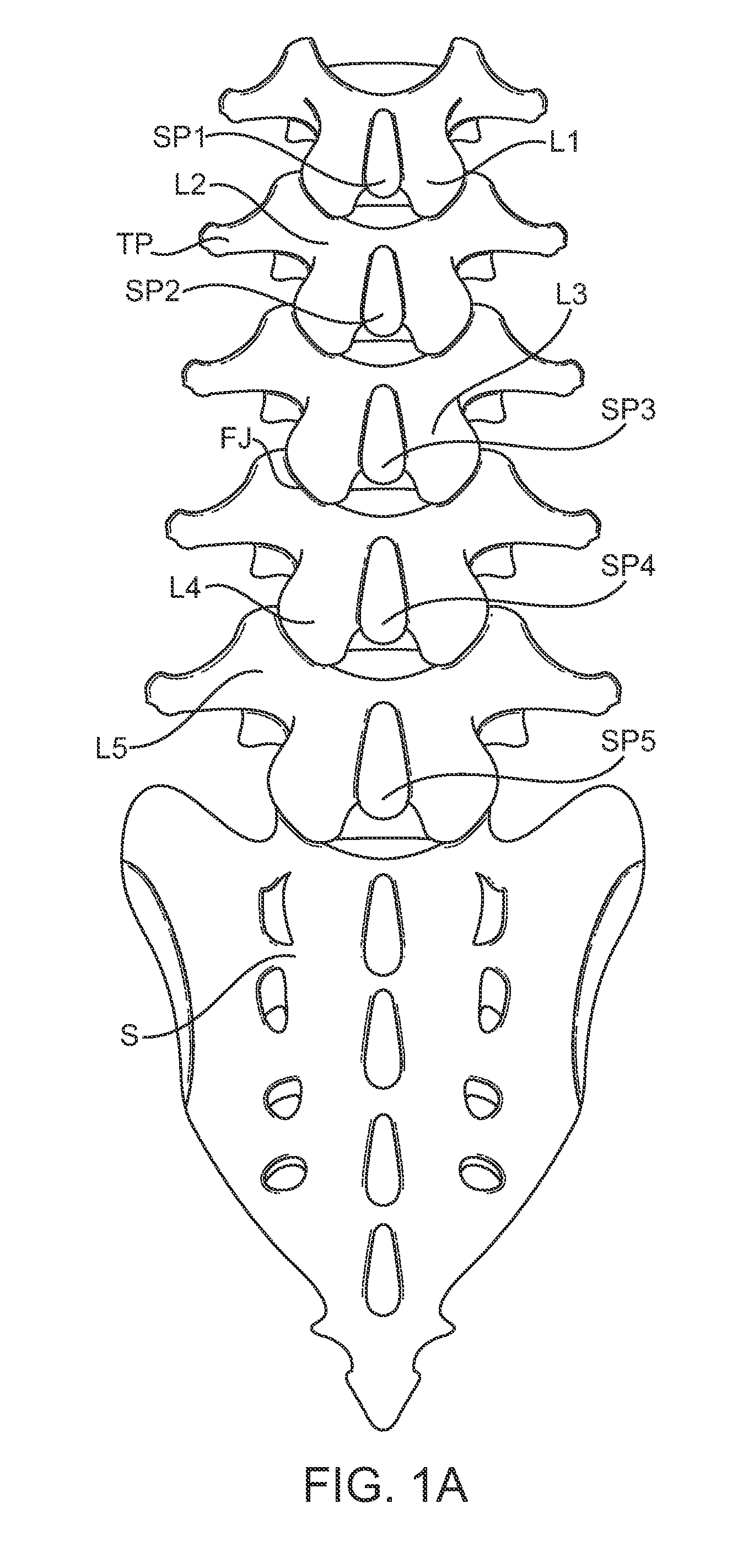
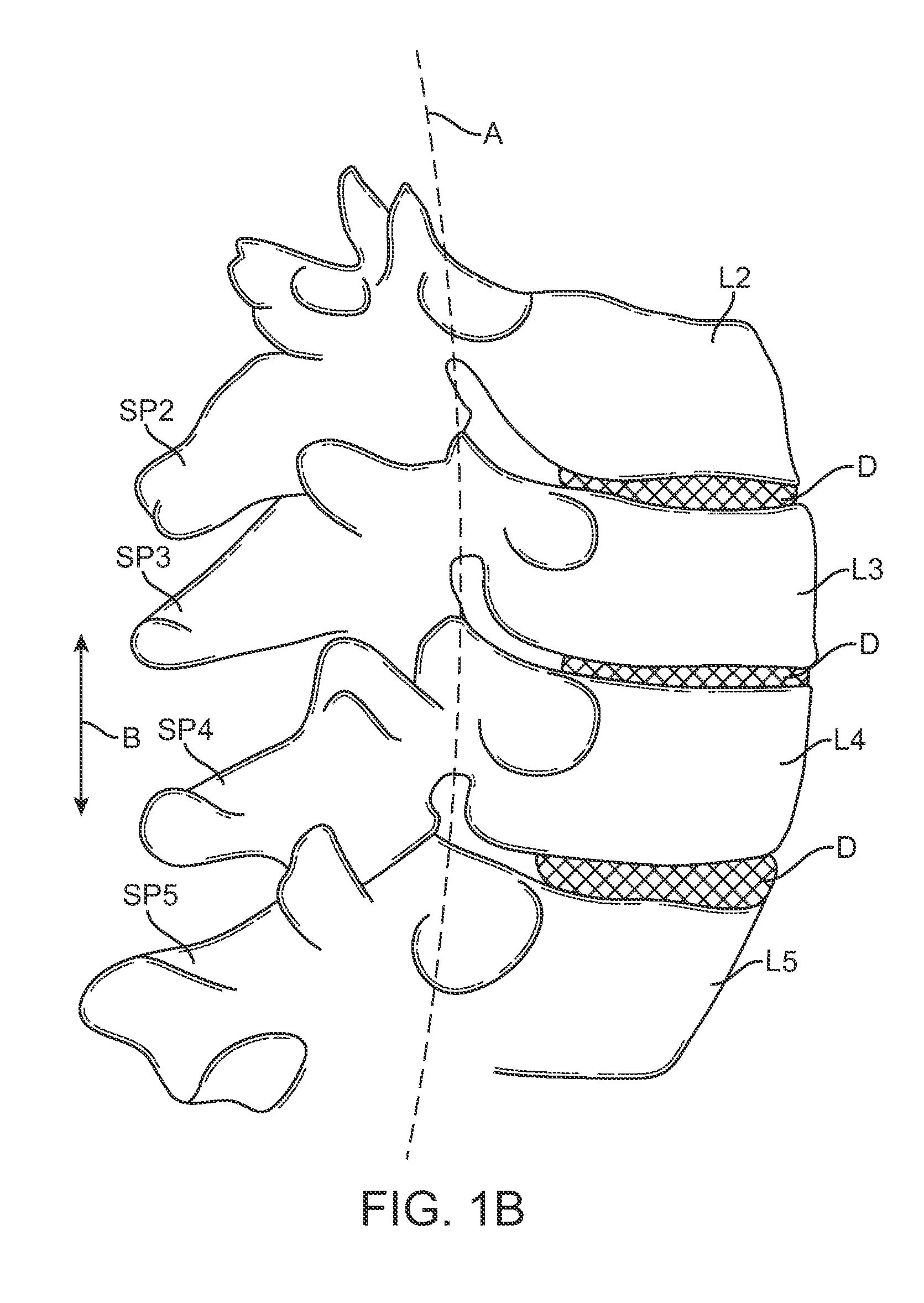
[0027]FIG. 1A is a schematic diagram illustrating the lumbar region of the spine including the spinous processes (SP), facet joints (FJ), lamina (L), transverse processes (TP), and sacrum (S). FIG. 1B is a schematic illustration showing a portion of the lumbar region of the spine taken along a sagittal plane and is useful for defining the terms “neutral position,”“flexion,” and “extension” that are often used in this disclosure.

[0028]As used herein, “neutral position” refers to the position in which the patient's spine rests in a relaxed standing position. The “neutral position” will vary from patient to patient. Usually, such a neutral position will be characterized by a slight curvature or lordosis of the lumbar spine where the spine has a slight anterior convexity and slight posterior concavity. In some cases, the presence of the constraint of the present invention may modify the neutral position, e.g. the device may apply an initial force which defines a “new” neutral position h...


PUM


Abstract

Methods and apparatus for controlling flexion in a spinal segment of a patient include performing a spinal fusion procedure on a pair of adjacent vertebrae in the spinal segment and implanting a constraint device into the patient. Adjusting length or tension in the constraint device allows the constraint device to provide a force a force resistant to flexion of the spinal segment undergoing fusion. The constraint device also modulates loads borne by the spinal segment undergoing fusion or tissue adjacent thereto.

Description

CROSS-REFERENCES TO RELATED APPLICATIONS[0001]The present application is a non-provisional of, and claims the benefit of U.S. Provisional Patent Application No. 61 / 158,886 (Attorney Docket No. 026398-001400US) filed Mar. 10, 2009, the entire contents of which are incorporated herein by reference. The present application is also related to the U.S. Provisional Patent Application No. 61 / 158,892 (Attorney Docket No. 026398-001300US) filed Mar. 10, 2009, the entire contents of which is incorporated herein by reference.BACKGROUND OF THE INVENTION[0002]1. Field of the Invention[0003]The present invention generally relates to medical methods and apparatus. More particularly, the present invention relates to methods and apparatus used to restrict flexion of a fused spinal segment. The methods and apparatus disclosed herein may be used alone or in combination with fusion or other orthopedic procedures intended to treat patients with spinal disorders such as back pain.[0004]A host of spinal c...

Claims


Application Information

Patent Timeline
Patent Type & Authority Applications(United States)
IPC IPC(8): A61B17/88A61F2/44
CPCA61B17/7055A61B17/7062A61F2/4455A61B17/7097A61F2/442A61B17/7067
Inventor ALAMIN, TODDCAHILL, COLINFIELDING, LOUISKOTHARI, MANISH
Owner SIMPIRICA SPINE
Why Eureka
Try Eureka