Self-calibrated, remote imaging and data processing system

a data processing system and self-calibration technology, applied in the field of remote imaging techniques, to achieve the effect of improving output quality

Active Publication Date: 2010-09-16
VI TECH LLC
View PDF99 Cites 38 Cited by
  • Summary
  • Abstract
  • Description
  • Claims
  • Application Information

AI Technical Summary

Benefits of technology

[0009]The system may also include an Attitude Measurement Unit (AMU) such as inertial, optical, or similar measurement units communicatively connected to the computer consoles and the camera array assemblies. The AMU may determine the yaw, pitch, and/or roll of the aircraft at any instant in time and successive DGPS positions may be used to measure the vehicle heading with relation to geodesic north. The AMU data is integrated with the precision DGPS data to produce a robust, real-time AMU system. The system may further include a mosaicing module housed within the computer consoles. The mosaicing module includes a first component for performing initial processing on an input image. The mosaicing module also includes a second component for determining geographical boundaries of an input image with the second component being cooperatively engaged with the first component. The mosaicing module further includes a third component for mapping an input image into the composite image with accurate geographical position. The third component being cooperatively engaged with the first and second components. A fourth component is also included in the mosaicing module for balancing color of the input images mapped into the composite image. The fourth component can be cooperatively engaged with the first, second and third compone

Problems solved by technology

Vibrations, turbulence, and other forces may act on the vehicle in such

Method used


Image

  • Self-calibrated, remote imaging and data processing system
  • Self-calibrated, remote imaging and data processing system
  • Self-calibrated, remote imaging and data processing system

Examples


Embodiment Construction

[0036]While the making and using of various embodiments of the present invention are discussed in detail below, it should be appreciated that the present invention provides many applicable inventive concepts, which can be embodied in a wide variety of specific contexts. The specific embodiments discussed herein are merely illustrative of specific ways to make and use the invention and do not limit the scope of the invention.

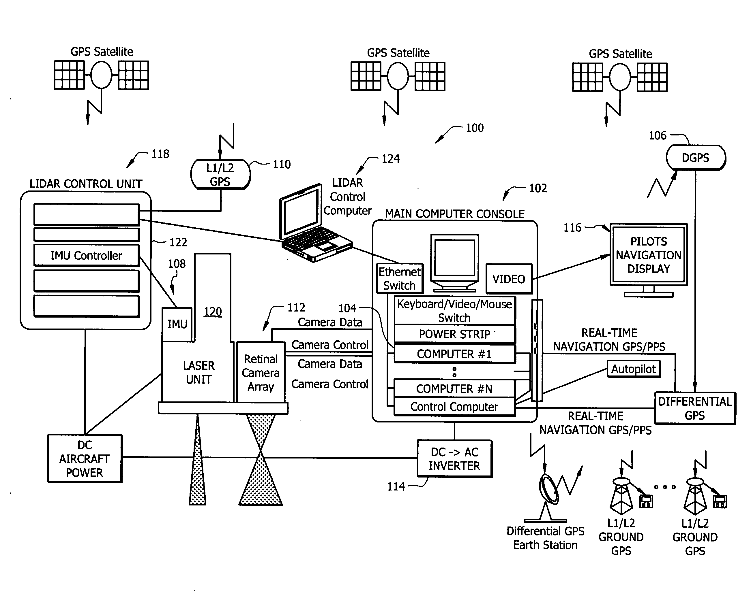
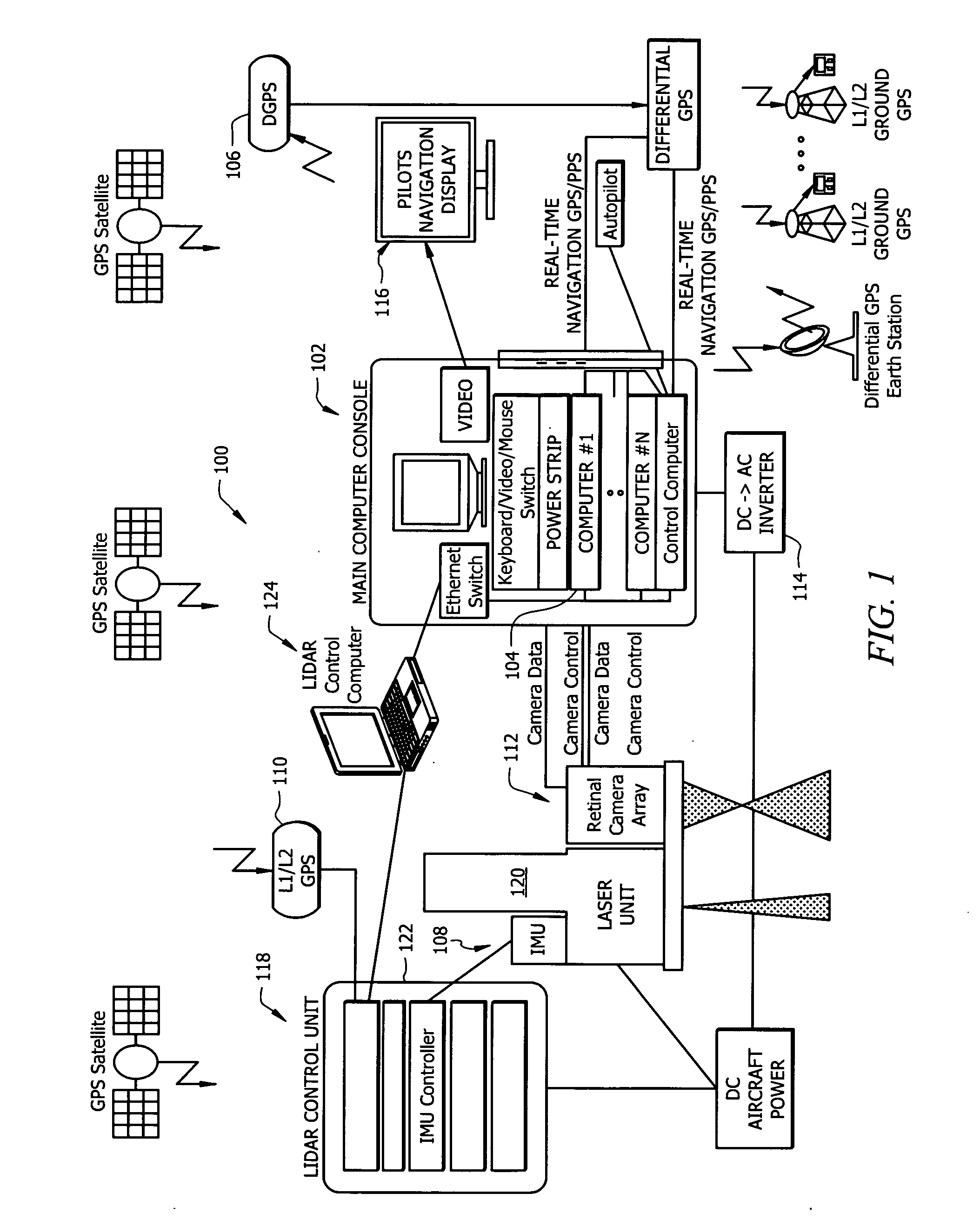
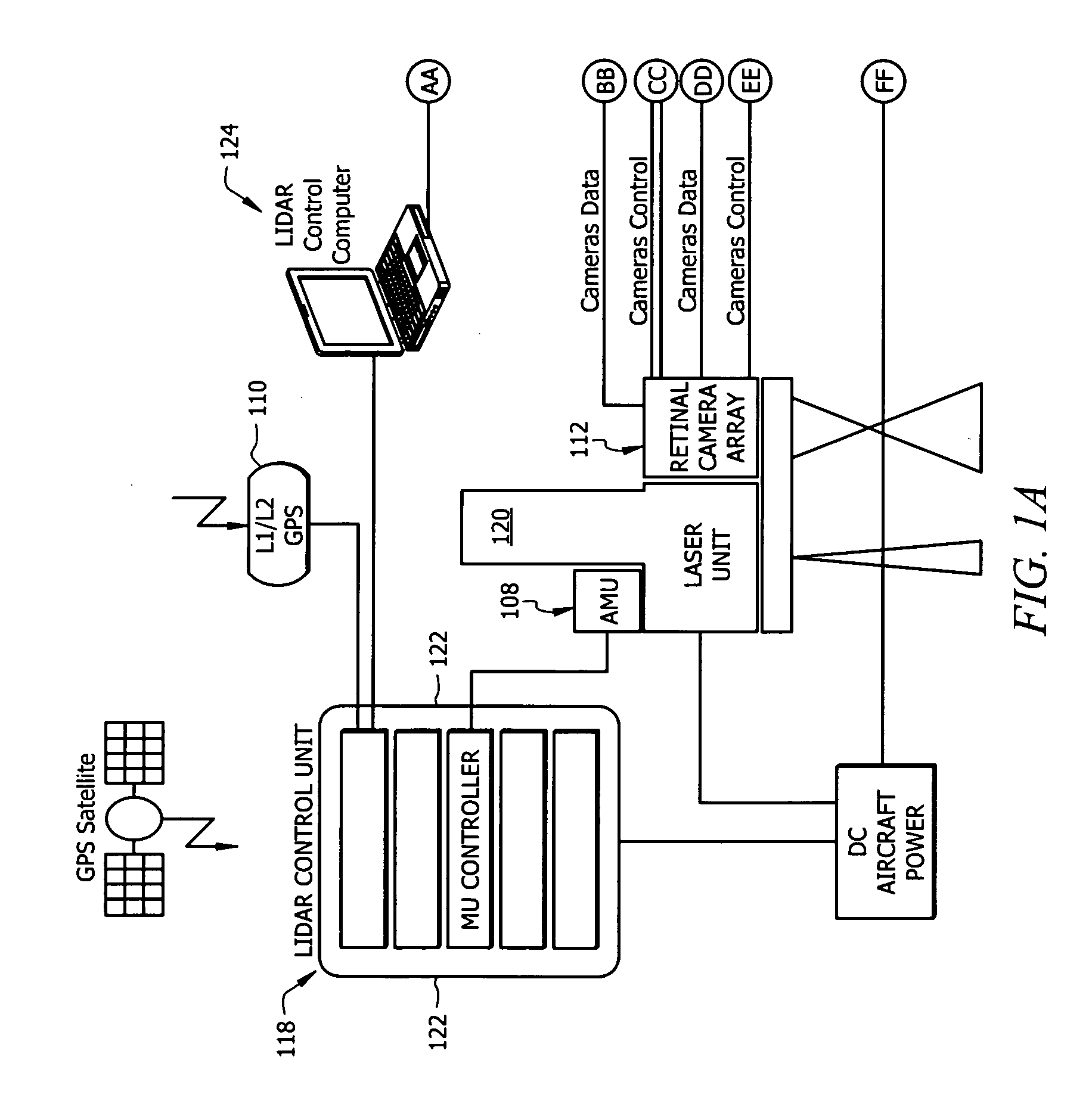
[0037]A vehicle based data collection and processing system 100 of the present invention is shown in FIGS. 1, 1A, and 1B. Additional aspects and embodiments of the present invention are shown in FIGS. 2 and 18. System 100 includes one or more computer consoles 102. The computer consoles contain one or more computers 104 for controlling both vehicle and system operations. Examples of the functions of the computer console are the controlling digital color sensor systems that can be associated with the data collection and processing system, providing the display dat...


PUM


Abstract

An imaging sensor system comprising: a rigid mount plate affixed to a vehicle; a first rigid mount unit affixed to the mount plate and having at least two imaging sensors disposed within the first mount unit, wherein a first imaging and a second imaging sensor each has a focal axis passing through an aperture in the first mount unit and the mount plate, wherein the first and second imaging sensor each generates a first array of pixels, wherein each array of pixels is at least two dimensional, wherein the first and second imaging sensors are offset to have a first image overlap area in the target area, wherein the first sensors image data bisects the second sensors image data in the first image overlap area.

Description

CROSS-REFERENCE TO RELATED APPLICATION[0001]This application is a continuation-in-part of U.S. patent application Ser. No. 11 / 581,235, filed on Oct. 11, 2006, which claimed priority to U.S. patent application Ser. No. 10 / 664,737, filed on Sep. 18, 2003, which claimed priority to U.S. Provisional Patent Application Ser. No. 60 / 412,504, filed on Sep. 20, 2002 for “Vehicle Based Data Collection and Processing System.”TECHNICAL FIELD OF THE INVENTION[0002]The present invention relates, generally, to the field of remote imaging techniques and, more particularly, to a system for rendering high-resolution, high accuracy, low distortion digital images over very large fields of view.BACKGROUND OF THE INVENTION[0003]Remote sensing and imaging are broad-based technologies having a number of diverse and extremely important practical applications—such as geological mapping and analysis, and meteorological forecasting. Aerial and satellite-based photography and imaging are especially useful remot...

Claims


Application Information

Patent Timeline
IPC IPC(8): G01C21/00G01S19/42G06F19/00G01S17/86G01S17/89
CPCG01C11/02G01S7/4811G01S17/023G01S17/88G01S17/89G01S7/4972G01S19/41G03B37/04G01S3/7803H04N17/002G01S19/14G01S17/86H04N23/45H04N23/51H04N23/54G01C21/20
Inventor SMITHERMAN, CHESTER L.
Owner VI TECH LLC
Why Eureka
Try Eureka