Air conditioner

a technology for air conditioners and motors, applied in the field of air conditioners, can solve the problems of large size of the moving space of the unit and the size of the driving motor of the uni

Active Publication Date: 2010-09-23
FUJITSU GENERAL LTD
View PDF37 Cites 2 Cited by
  • Summary
  • Abstract
  • Description
  • Claims
  • Application Information

AI Technical Summary

Problems solved by technology

In the case of moving the cleaning unit, the sizes of the movi

Method used


Image

  • Air conditioner
  • Air conditioner
  • Air conditioner

Examples


Embodiment Construction

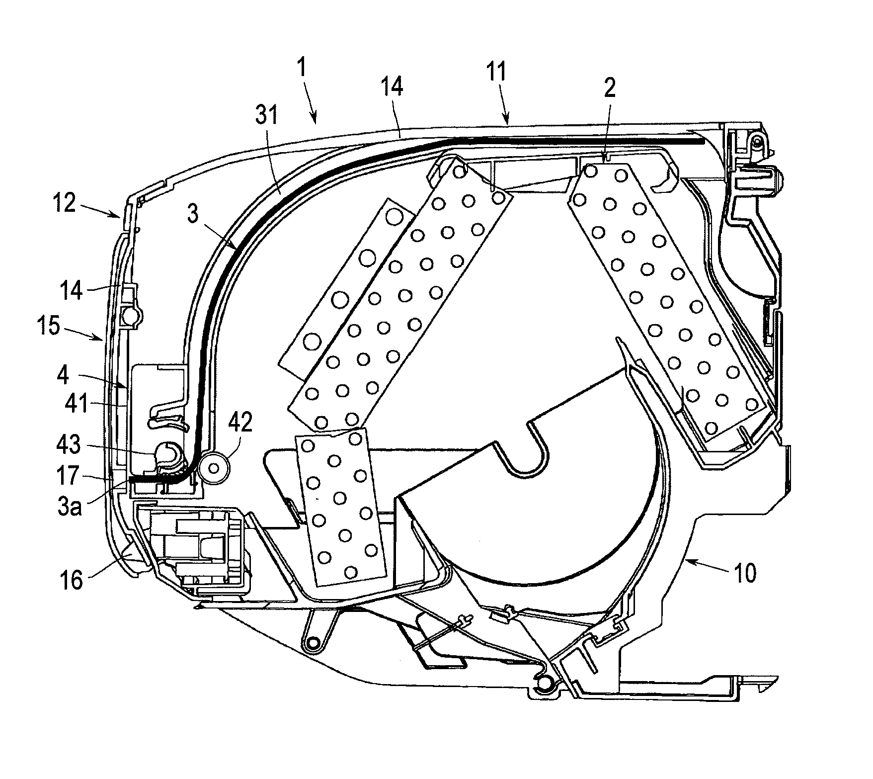
[0033]Although an embodiment of the invention will be explained hereinafter with reference to drawings, the invention is not limited thereto. As shown in FIG. 1, the indoor unit 1 of the air conditioner according to the embodiment is provided with a base panel 10 supported by a wall surface via a not-shown rear plate.

[0034]A heat exchanger 2 and a cross flow fun (not shown) are supported by the base panel 10 so as to be bridged thereover. According to the invention, since the concrete configuration of each of the heat exchanger 2 and the cross flow fun is arbitral, the explanation thereof will be omitted.

[0035]Although an air blowout port, a wind direction plate, a diffuser (each not shown) etc. are provided on the lower surface side of the base panel 10, since the configurations thereof are not limited in particular in the invention, the explanation thereof will also be omitted.

[0036]The base panel 10 is provided with an upper panel 11 for covering the upper surface of the heat exc...


PUM


Abstract

The filter 3 is extruded to the outside of the casing of the air conditioner along the inner side of an open panel 15 which is provided at the front surface side of an air intake grill 14 and opened/closed at the time of the operation of the air conditioner.

Description

CROSS-REFERENCE TO RELATED APPLICATION[0001]This application is based on and claims priority under 35 U.S.C. §119 from Japanese Patent Application No. 2009-068876 filed on Mar. 19, 2009.BACKGROUND OF THE INVENTION[0002]1. Technical Field[0003]The present invention relates to an air conditioner (indoor unit) having a function of automatically cleaning a filter and, more particularly, relates to an air conditioner which casing is miniaturized by improving the moving path of the filter.[0004]2. Related Art[0005]For example, as shown in a patent document 1, some types of the indoor units of recent air conditioners have a filter cleaning function for automatically removing dust adhered to a filter.[0006]In general, the filter cleaning function is realized in a manner that there are provided with a filter attached to a main body cabinet so as to cover an air intake port and a cleaning unit for collecting dust adhered to the filter, whereby the filter is moved within the cleaning unit to t...

Claims


Application Information

Patent Timeline
IPC IPC(8): F25D31/00F24F1/0073F24F13/28
CPCB01D41/04B01D46/0065B01D46/0072B01D46/48F24F2001/0048F24F2003/1639F24F2011/0068F24F1/0007F24F13/28B01D2279/50F24F11/56F24F1/0057F24F8/90F24F1/0073B01D46/74B01D46/681
Inventor SUGIYAMA, SHINJISHIBUYA, MAKOTONOJIMA, AKIHIKO
Owner FUJITSU GENERAL LTD
Why Eureka
Try Eureka