Dry-coupled permanently installed ultrasonic sensor linear array

a technology of ultrasonic sensors and linear arrays, applied in the direction of instruments, magnetic property measurements, analysing solids using ultrasonic/ultrasonic/infrasonic waves, etc., can solve the problems of signal loss or inaccurate reading, high manufacturing cost of ultrasonic sensors, signal problems

Inactive Publication Date: 2010-09-23
BP CORP NORTH AMERICA INC
View PDF18 Cites 36 Cited by
  • Summary
  • Abstract
  • Description
  • Claims
  • Application Information

AI Technical Summary

Problems solved by technology

Conventional ultrasonic sensors have high manufacturing costs and have coupling issues or problems resulting in loss of signal or inaccurate readings.
The liquid couplant dries, leaks, and/or runs out from the under the

Method used


Image

  • Dry-coupled permanently installed ultrasonic sensor linear array
  • Dry-coupled permanently installed ultrasonic sensor linear array
  • Dry-coupled permanently installed ultrasonic sensor linear array

Examples


example 1

Prior Art

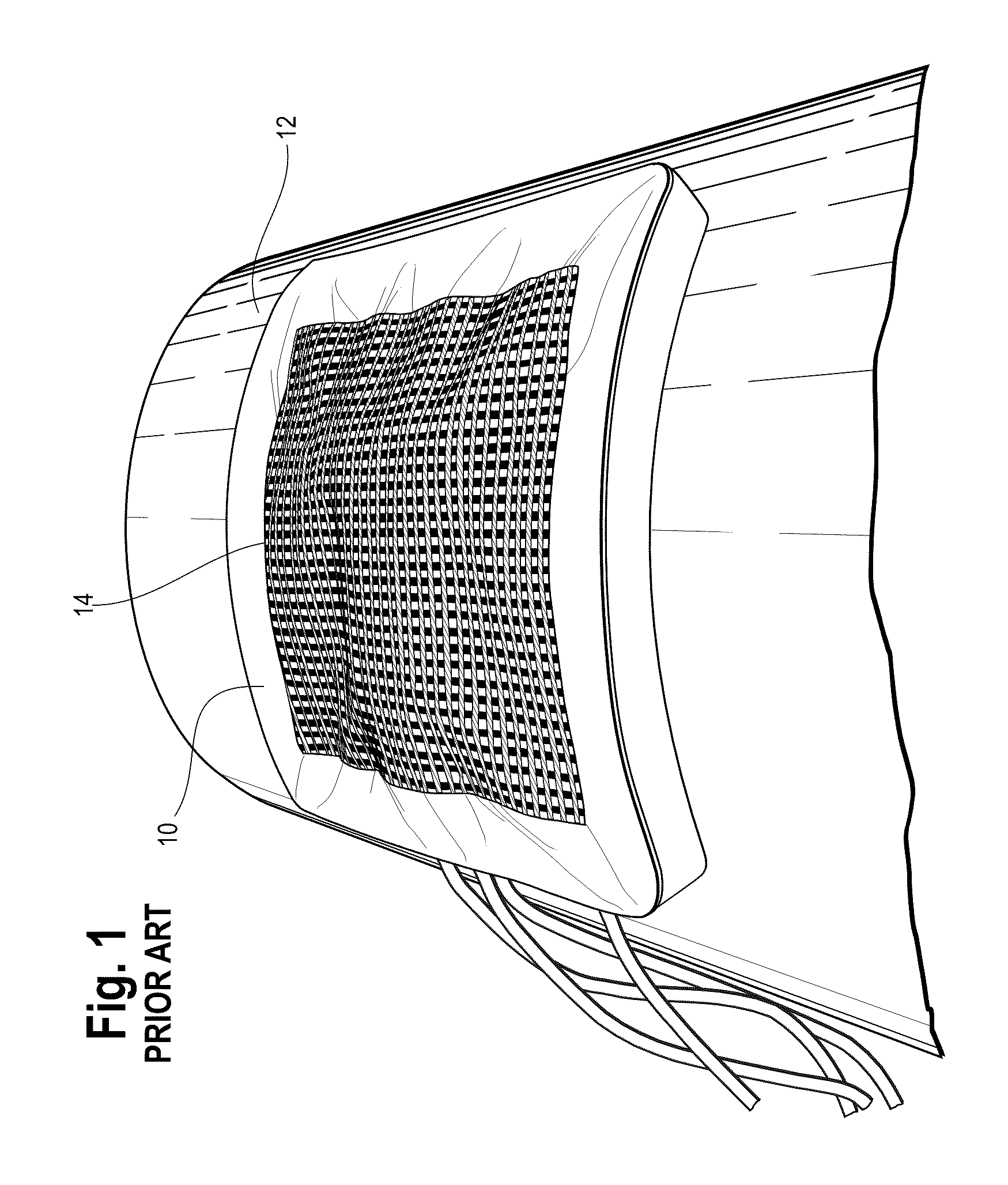
[0066]A known flexible ultrasonic array 10 has a square configuration of ultrasonic transducer elements vacuum attached to a pipe 12, as shown in FIG. 1. The array 10 of FIG. 1 included 1024 transducer elements 14 having 0.25 inch (6.35 mm)×0.25 inch (6.35 mm) size and arranged in a 32×32 square element matrix. The array 10 was vacuum coupled to a 12 inch (30.5 cm) diameter pipe 12. The dimensions of the active area of the array 10 were 8 inches (20.3 cm) by 8 inches (20.3 cm) for a total inspection area of 64 square inches (162.6 cm squared). Vacuum couplings did not provide a permanent mounting solution and failed due to leakage and / or thermal cycling.

example 2

0 Degree Wall Thickness Array

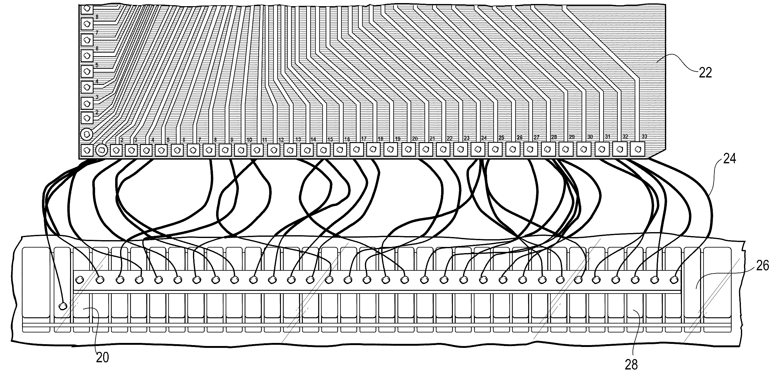
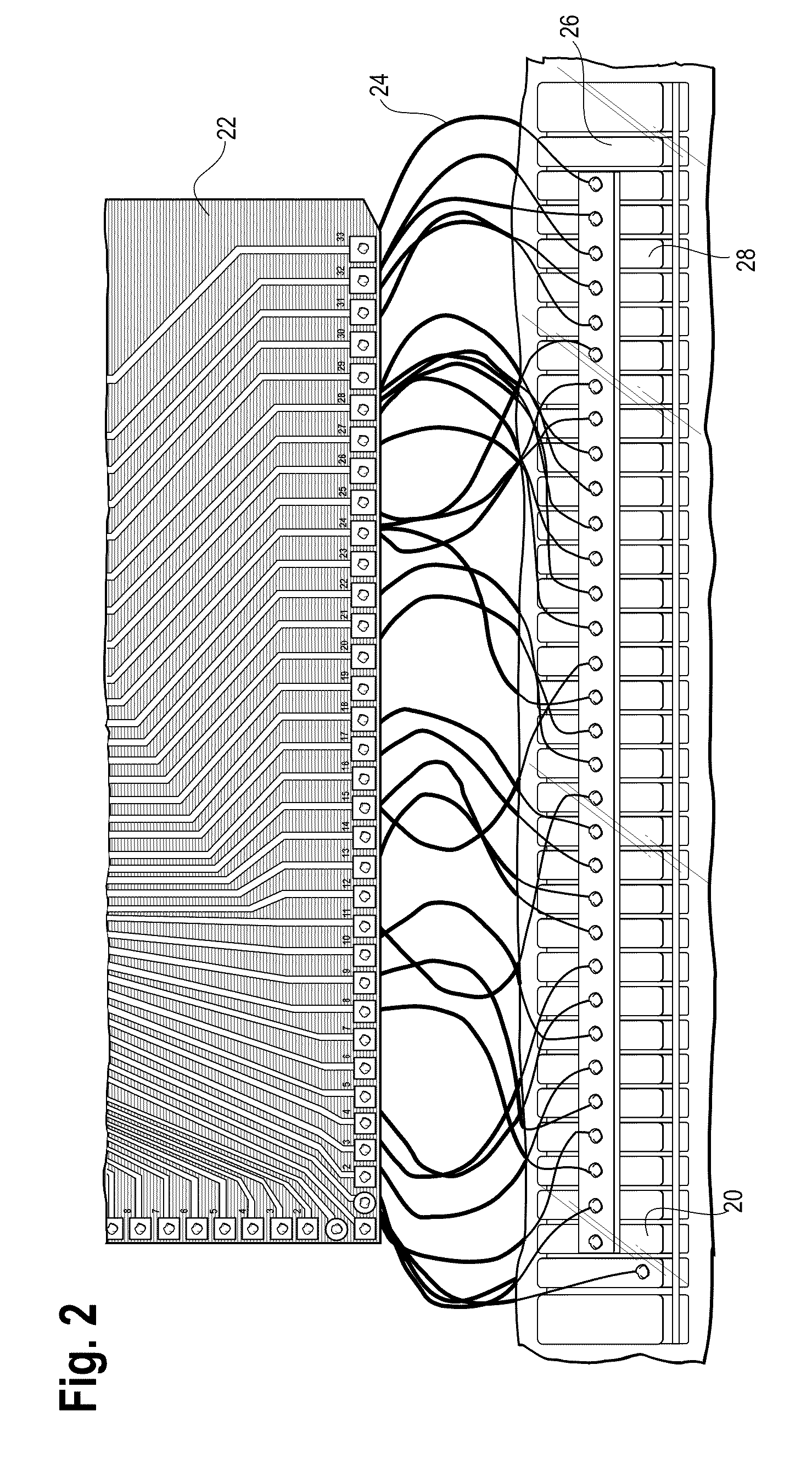
[0067]As shown in FIG. 2, a first prototype was constructed in 0 (zero) degree (angle of incidence) configuration. The 0 degree linear array 20 was tested using a 32 channel Array Scanner (not shown) from HD Laboratories, Inc (Issaquah, Wash. USA) by attaching an 8 inch×8 inch (203 mm×203 mm) blanket circuit board 22 with wires 24. The scanner stores and / or places in memory all scanned data. The device could be configured to display any combination of the “A”, “B-X”, “B-Y”, “C”, and “C-TOF”. Once the scan is stored, the gates were manipulated to study any portion of the scan. Tests were conducted with dry-coupled interfaces 26, where no wet couplants, adhesives and / or vacuum pressure were used to assist with ultrasonic transmission. The tests were performed at room temperature.

[0068]The linear array of this invention was fabricated with a 0 degree wall thickness configuration in FIG. 2. The 0 degree array 20 for sensing wall thickness included thirty-two...

example 3

TOFD Array

[0069]A second prototype was constructed as above except configured to be a TOFD array 42 with thirty-two 8 MHz ¼ inch (6.35 mm) diameter elements or sensors 44 for both the transmitters and the receivers mounted on a dry-coupling 46 of RTV 615 segmented in a wedge strip, as shown in FIG. 5. The TOFD array 42 as shown in FIG. 5 is connected to an 8 inch x 8 inch (203 mm×203 mm) array circuit board 48 for testing with the scanner (not shown) with wires 50. The wedges were cast to the correct incident angle in molds. Due to the large sonic velocity difference between the RTV615 and the carbon steel, the mold angles were controlled to tight tolerances.

[0070]A chip mounting and a chip placement mold was designed and fabricated as shown in FIG. 6. FIG. 6 shows the molds 30, such as where the lower mold is typical of the segmented wedge molds 30. A chip alignment tool is shown at the top of FIG. 6.

[0071]FIG. 7 shows a notched test block 54 with a series of cracks or notches 56 t...


PUM


Abstract

This invention relates to permanent, ultrasonic, flexible, dry-coupled, linear arrays for the inspection of pipelines, process equipment, and the like. The permanent, ultrasonic, flexible, dry-coupled, linear arrays detect and/or measure corrosion wall loss, stress corrosion cracking, and/or internal initiated pipeline cracking. The apparatus for ultrasonically testing materials includes a linear array of ultrasonic sensors, and a flexible, acoustically transmissive, dry-coupling surrounding at least a portion of each of the ultrasonic sensors.

Description

BACKGROUND[0001]1. Field of the Invention[0002]This invention relates to permanent, ultrasonic, flexible, dry-coupled, linear arrays for the inspection of pipelines, process equipment, and the like. The permanent, ultrasonic, flexible, dry-coupled, linear arrays detect and / or measure corrosion wall loss, stress corrosion cracking, and / or internal initiated pipeline cracking.[0003]2. Discussion of Related Art[0004]Conventional ultrasonic sensors have high manufacturing costs and have coupling issues or problems resulting in loss of signal or inaccurate readings. Good ultrasonic sound transmission depends upon removing all air between the sensor and a test surface. Sufficient readings and / or measurements involve the ultrasonic sensor transmitting and receiving a signal with minimal signal loss and / or degradation, such as without air bubbles and / or gaps. Ultrasonic sensors typically use a couplant to increase transmission between a test material and the sensor. Conventional liquid coup...

Claims


Application Information

Patent Timeline
IPC IPC(8): G01N29/04
CPCG01N29/223G01N29/2487G10K11/02G01N2291/106G01N29/28
Inventor NYHOLT, JOHNLANGLOIS, GARY N.
Owner BP CORP NORTH AMERICA INC
Why Eureka
Try Eureka