Vehicle cooling controller and cooling control method

a technology for vehicle cooling and controllers, applied in the direction of machines/engines, mechanical equipment, transportation and packaging, etc., can solve the problems of power consumption and load on the battery, unfavorable engine start characteristics, and possible overheating of cooling water, etc., to achieve good starting characteristics of the engine

Active Publication Date: 2010-09-23
TOYOTA JIDOSHA KK
View PDF1 Cites 42 Cited by
  • Summary
  • Abstract
  • Description
  • Claims
  • Application Information

AI Technical Summary

Benefits of technology

[0022]According to the present invention, even if the temperature of heat exchanger is high because of exhaust heat, the engine coolant temperature may be low and the engine is not well warmed. In such a situation, if it is estimated that the time period from engine stop to engine restart is s...

Problems solved by technology

Therefore, the cooling water may possibly be overheated and boiled.
If the electric water pump is operated after the engine s...

Method used


Image

  • Vehicle cooling controller and cooling control method
  • Vehicle cooling controller and cooling control method
  • Vehicle cooling controller and cooling control method

Examples


first embodiment

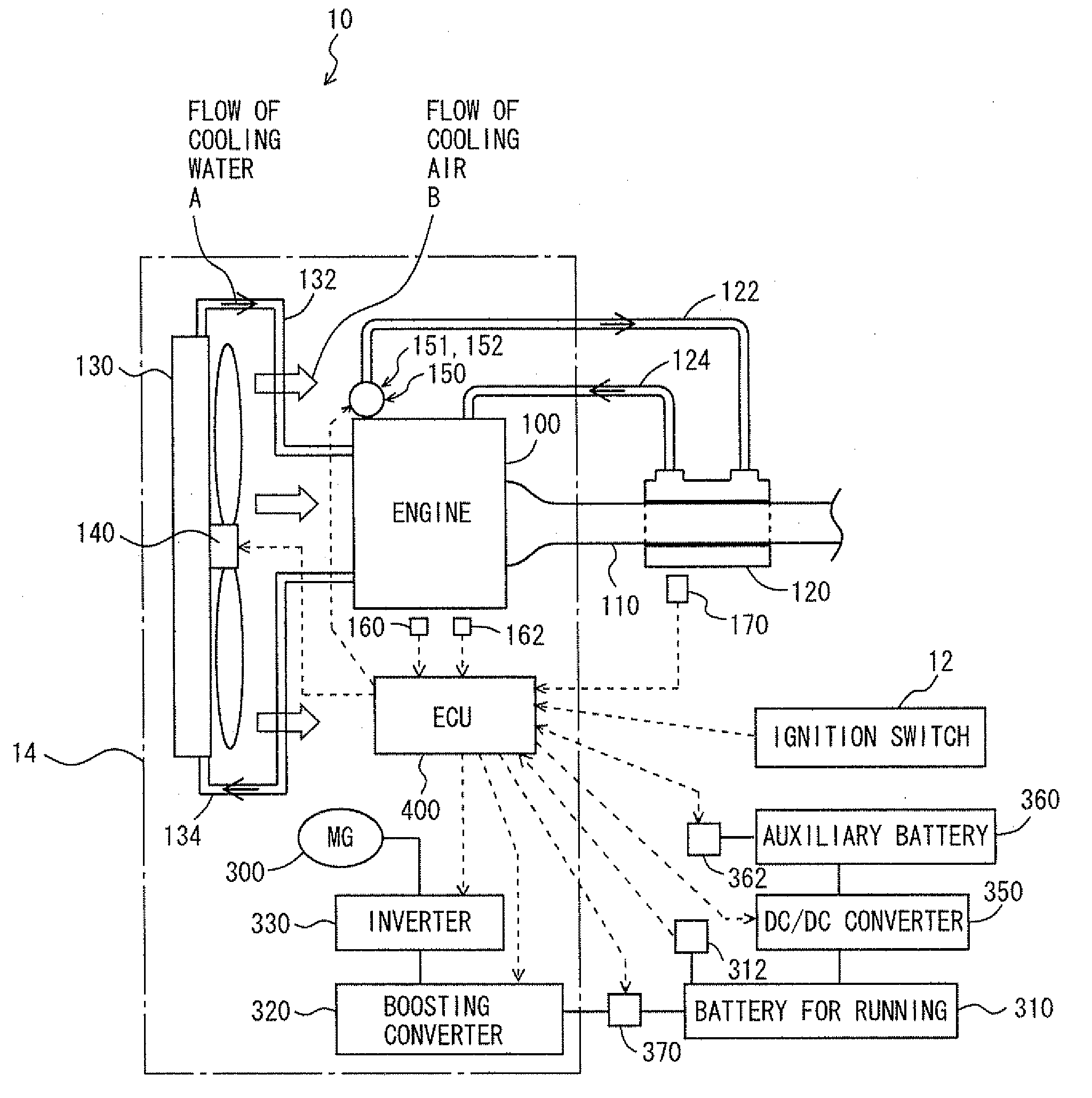
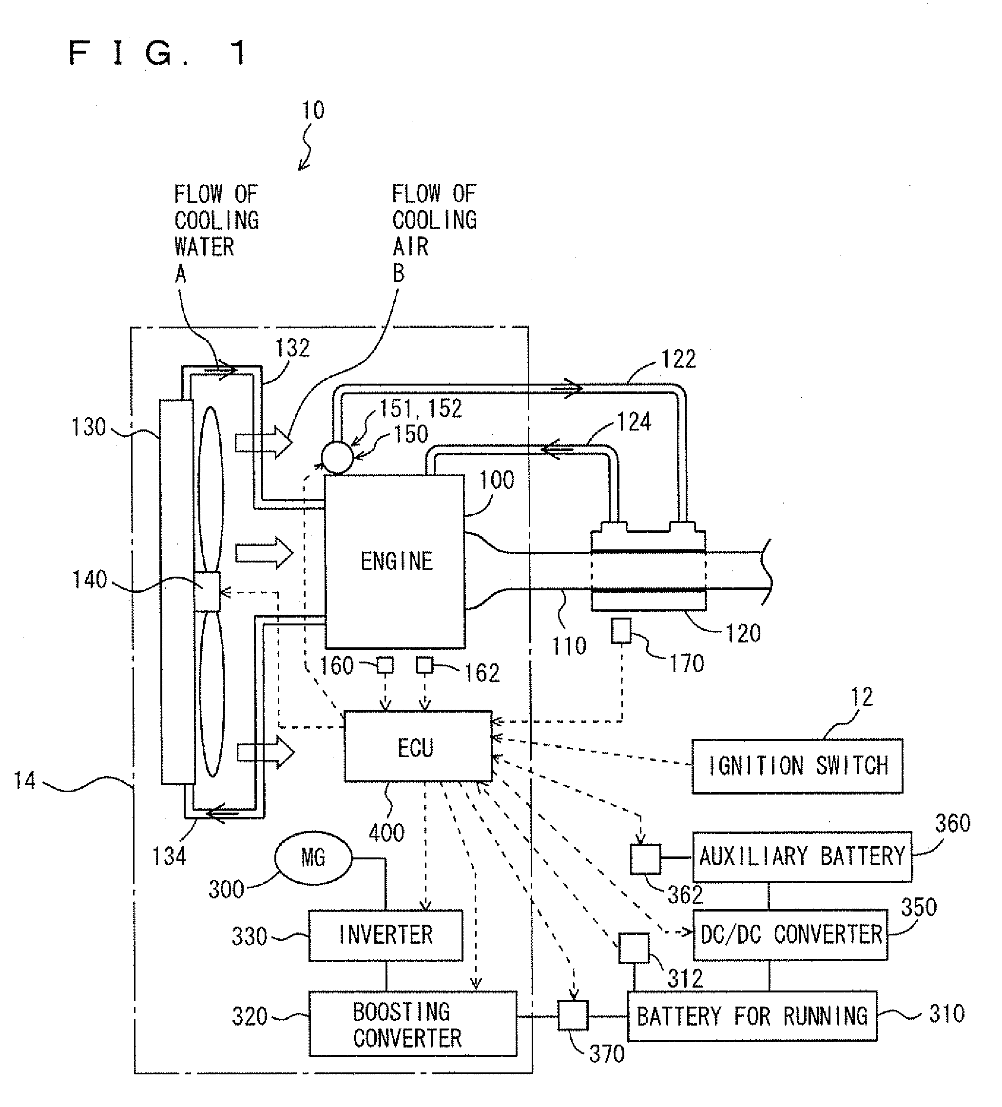
[0036]Referring to FIG. 1, a hybrid vehicle 10 provided with the cooling controller in accordance with the present embodiment will be described. The vehicle to which the cooling controller of the present invention is applicable is not limited to the hybrid vehicle shown in FIG. 1, and it may be a different type hybrid vehicle or may be a common engine vehicle.

[0037]Hybrid vehicle 10 includes an engine 100, a motor generator 300, a battery 310 for running, storing electric power for driving motor generator 300, an inverter performing current control by conversion between DC of battery 310 for running and AC of motor generator 300, a boosting converter 320 for boosting electric power when electric power is supplied from battery 310 for running to motor generator 300, an auxiliary battery 360, a DC / DC converter 350, an SMR (System Main Relay) 370 provided between battery 310 for running and boosting converter 320, and an ECU 400 for overall control of the hybrid system to realize the m...

second embodiment

[0108]In the following, a cooling controller in accordance with the present embodiment will be described. A hybrid vehicle 20 provided with the cooling controller in accordance with the present embodiment has a structure different from the structure of hybrid vehicle 10 described in the first embodiment above, in that it further includes a temperature sensor 180 and includes an ECU 1400 in place of ECU 400, as shown in FIG. 8. ECU 1400 is different from ECU 400 in that temperature sensor 180 is further connected and that the program executed therein has a different control structure. Except for these points, the structure is the same as that of hybrid vehicle 10 in accordance with the first embodiment described above. The same components are denoted by the same reference characters. Their functions are also the same. Therefore, detailed description thereof will not be repeated here.

[0109]Temperature sensor 180 detects internal temperature TC of engine compartment 14, and transmits a...


PUM


Abstract

A drive component for driving an electric water pump for causing engine coolant to flow is mounted in an engine compartment. When the ignition is off and the temperature of a exhaust heat recovery device is above a temperature, an ECU estimates a peak temperature in the engine compartment after the stop of the engine. When the peak temperature is above a temperature, the ECU stops the engine and drives the electric water pump and an electric fan for cooling the drive component for driving the electric water pump.

Description

TECHNICAL FIELD[0001]The present invention relates to control of cooling a vehicle provided with an electric water pump causing an engine coolant to flow and, more specifically, to vehicle cooling control in which the electric pump is driven after the engine is stopped when the vehicle is stopped.BACKGROUND ART[0002]A vehicle, in which cooling water is circulated in an engine using an electric water pump to keep the engine at a suitable temperature while the engine is driven to run the vehicle has been known. When the engine stops and the electric water pump is stopped simultaneously, it follows that the cooling water circulation stops while the engine is not sufficiently cooled yet. Therefore, the cooling water may possibly be overheated and boiled. If the electric water pump is operated after the engine stops in order to prevent boiling of cooling water, power consumption undesirably increases and load to the battery also increases. A solution to such a problem is disclosed, for e...

Claims


Application Information

Patent Timeline
IPC IPC(8): F01P7/00
CPCB60K6/48Y02T10/166B60L2240/445B60W10/06B60W10/30B60W20/00B60W2510/0638B60W2510/0676B60W2510/244B60W2540/06F01P7/04F01P7/164F01P2005/125F01P2025/48F01P2031/30F01P2050/24F01P2060/16F02G5/02F02G2280/10Y02T10/6221B60L2240/441Y02T10/12Y02T10/62
Inventor WATANABE, YOSHITAKAMIZUTANI, KOICHITOYOFUKU, NAOKIMOROZUMI, HIROKI
Owner TOYOTA JIDOSHA KK
Why Eureka
Try Eureka