Apparatus for and method of controlling internal combustion engine

Inactive Publication Date: 2010-09-23
HITACHI AUTOMOTIVE SYST LTD
View PDF11 Cites 32 Cited by
  • Summary
  • Abstract
  • Description
  • Claims
  • Application Information

AI Technical Summary

Benefits of technology

[0009]controls the variable valve mechanism based on the knocking occurrence condition, to the

Problems solved by technology

Incidentally, in the variable compression ratio mechanism that changes the piston top dead center position, there is a problem in that it has a complex structure

Method used


Image

  • Apparatus for and method of controlling internal combustion engine
  • Apparatus for and method of controlling internal combustion engine
  • Apparatus for and method of controlling internal combustion engine

Examples


Embodiment Construction

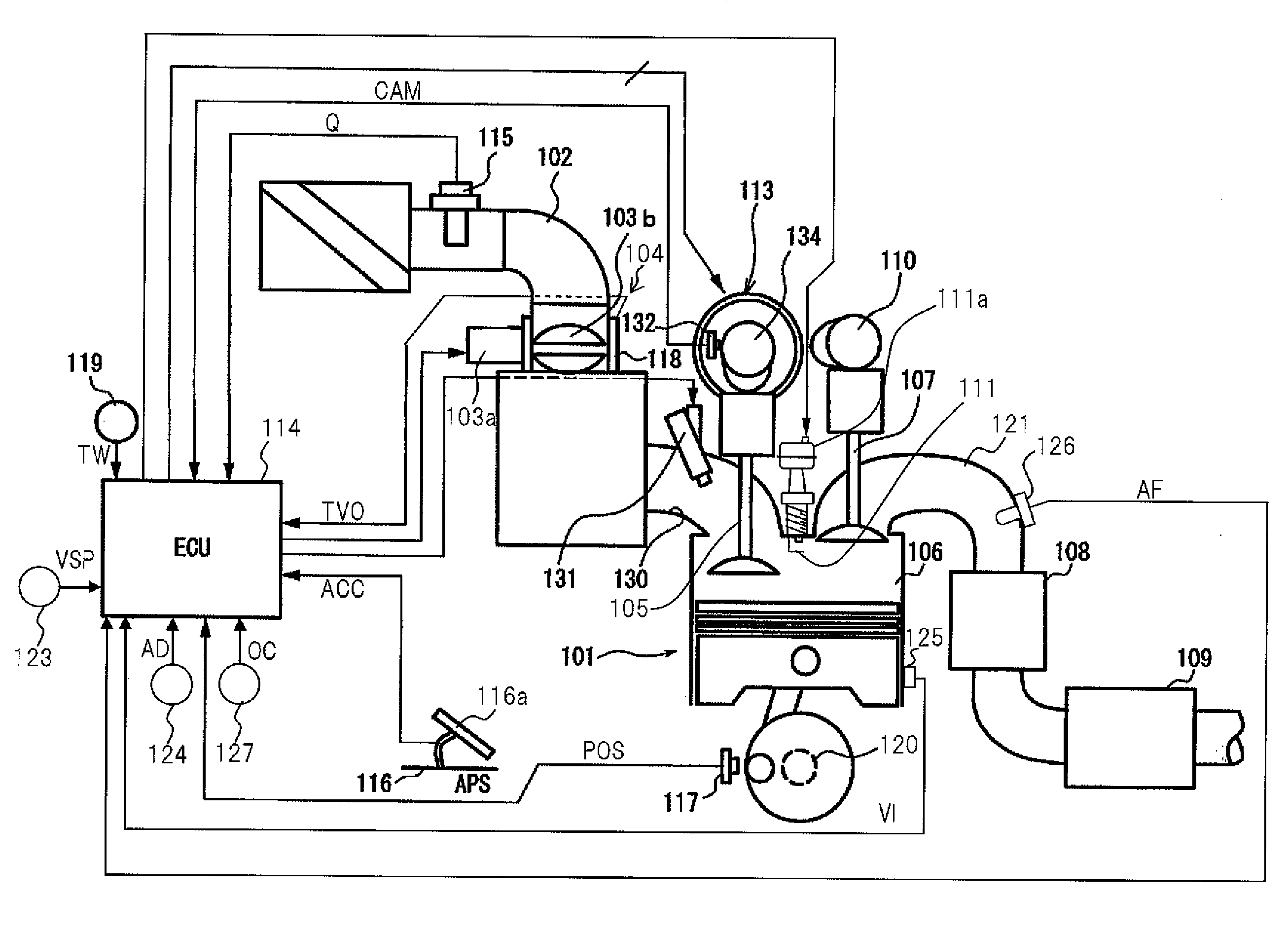
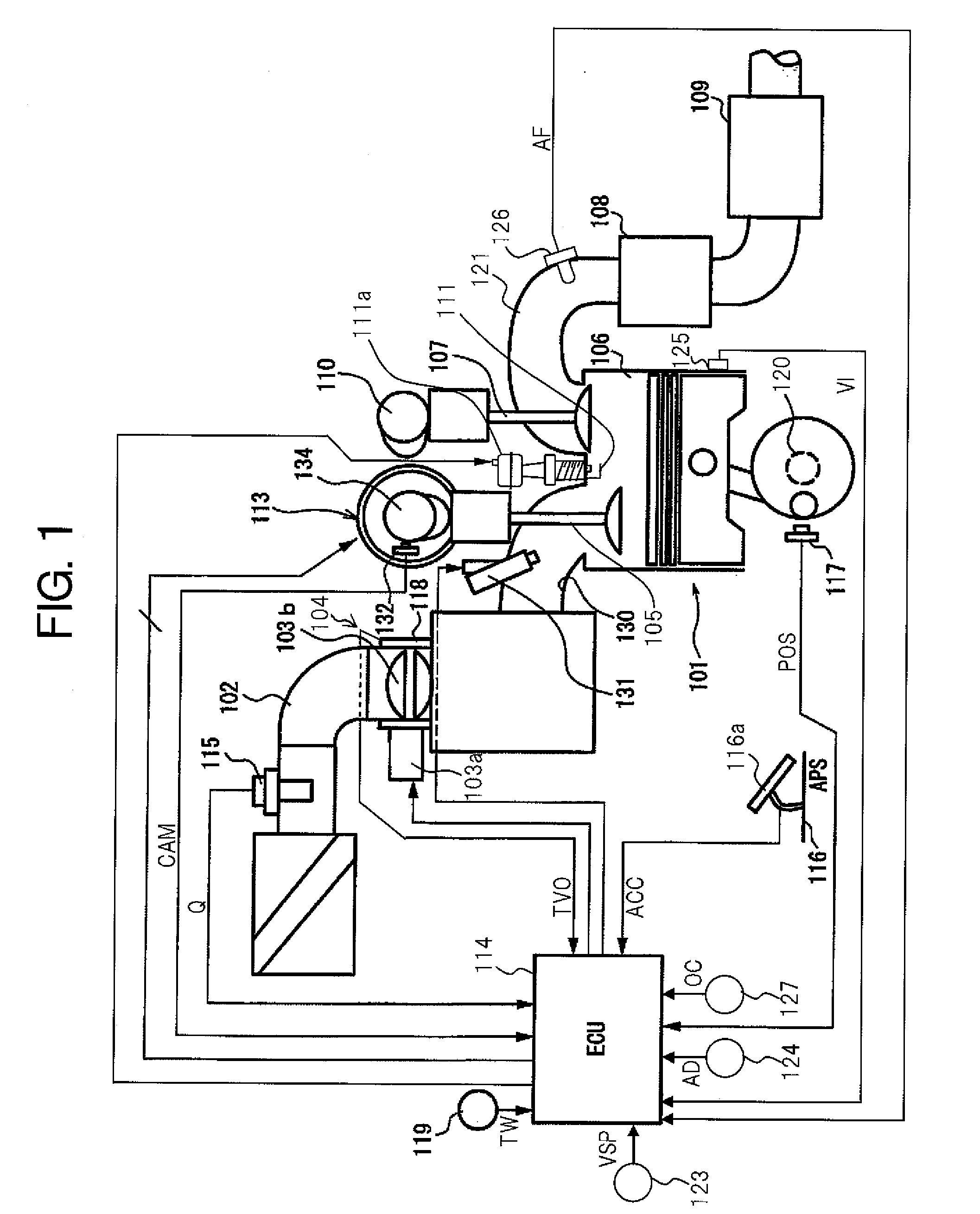
[0023]FIG. 1 is a block diagram of a vehicle internal combustion engine 101 to which a control apparatus according to the present invention is applied.

[0024]In internal combustion engine 101 shown in FIG. 1, in addition to gasoline, a mixed fuel of gasoline and alcohol may be used.

[0025]The mixed fuel may be stored in a fuel tank as a preliminarily mixed fuel, or gasoline and alcohol may be separately stored in fuel tanks, and then the gasoline and alcohol may be mixed when they are supplied to internal combustion engine 101.

[0026]Internal combustion engine 101 in the present embodiment is an inline four-cylinder engine, however it may also be a V-type engine or a horizontally opposed engine. Moreover, the number of cylinders may be four or more.

[0027]On an inlet pipe 102 of internal combustion engine 101, there is provided an electronically controlled throttle 104 that drives a throttle valve 103b open and close with a throttle motor 103a.

[0028]Internal combustion engine 101 sucks...


PUM


Abstract

Control apparatus performs knocking suppression control in an internal combustion engine provided with a variable valve mechanism that is capable of varying a closing timing IVC of an inlet valve. The control apparatus, in a case in which an alcohol concentration and octane number of a fuel are low and knocking is likely to occur, controls the variable valve mechanism and retards the closing timing of the inlet valve from the bottom dead center TDC. Thereby, the effective compression ratio is reduced and knocking occurrence is consequently suppressed.

Description

BACKGROUND OF THE INVENTION[0001]1. Field of the Invention[0002]The present invention relates to a control apparatus applied to an internal combustion engine provided with a variable valve mechanism that is capable of varying a closing timing of an inlet valve.[0003]2. Description of Related Art[0004]In Japanese Unexamined Patent Publication No. 2000-073804, it is disclosed that in an internal combustion engine having a variable compression ratio mechanism, if knocking occurs, the compression ratio is reduced by the variable compression ratio mechanism.[0005]Incidentally, in the variable compression ratio mechanism that changes the piston top dead center position, there is a problem in that it has a complex structure and the cost thereof is high. Moreover, it is difficult to change the compression ratio with respect to a knocking occurrence, at a high level of responsiveness.SUMMARY OF THE INVENTION[0006]It is therefore an object of the present invention to provide a control apparat...

Claims


Application Information

Patent Timeline
IPC IPC(8): F02M7/00F01L1/34F02D41/00
CPCF01L1/34403F01L13/0026F02D13/0238F02D13/0261F02D2200/0611F02D35/027F02D41/0025F02D2041/001F02D35/02F02D19/0623F02D19/084F02D19/087Y02T10/12Y02T10/30
Inventor SARUWATARI, MASAYUKIKOBAYASHI, SATOSHI
Owner HITACHI AUTOMOTIVE SYST LTD
Why Eureka
Try Eureka