An integrated equalization and cdr adaptation engine with single error monitor circuit

a technology of equalization and cdr adaptation engine, applied in the direction of pulse technique, amplitude demodulation, line-fault/interference reduction, etc., can solve the problems of data signal distortion, general edge-based sampling technique, and worsening of isi

Active Publication Date: 2010-09-23
ORACLE INT CORP
View PDF20 Cites 54 Cited by
  • Summary
  • Abstract
  • Description
  • Claims
  • Application Information

AI Technical Summary

Benefits of technology

[0011]In a still further embodiment, the receiver adapts the post-cursor tap coefficient of the FIR and the coefficient of the DFE based on one quantity. In a still further embodiment, the receiver increases a pre-cursor tap coefficient setting in response to determining that the phase corresponds to a point earlier than the peak amplitude of the pulse response of the channel and decreases a pre-cursor tap coefficient setting in response to determining that the phase corresponds to a point later than the peak amplitude of the pulse response of the channel. In a still further embodiment, the receiver is integrated into a serializer / deserializer.

Problems solved by technology

During propagation, data signals may experience distortion due to bandwidth limitations, dispersion, etc. in the communication channel.
Generally speaking, ISI becomes worse as the speed of communication increases.
Unfortunately, edge-based sampling techniques generally increase the number of samples that must be taken in each cycle.
More sampling per cycle increases the circuitry required and the power consumption of SERDES elements.
Unfortunately, most current error-monitoring implementations require both mid-symbol and edge-based sampling, increasing circuitry and power consumption in a SERDES.
Unfortunately, these techniques only adapt the link for specific communications protocols.

Method used


Image

  • An integrated equalization and cdr adaptation engine with single error monitor circuit
  • An integrated equalization and cdr adaptation engine with single error monitor circuit
  • An integrated equalization and cdr adaptation engine with single error monitor circuit

Examples


Embodiment Construction

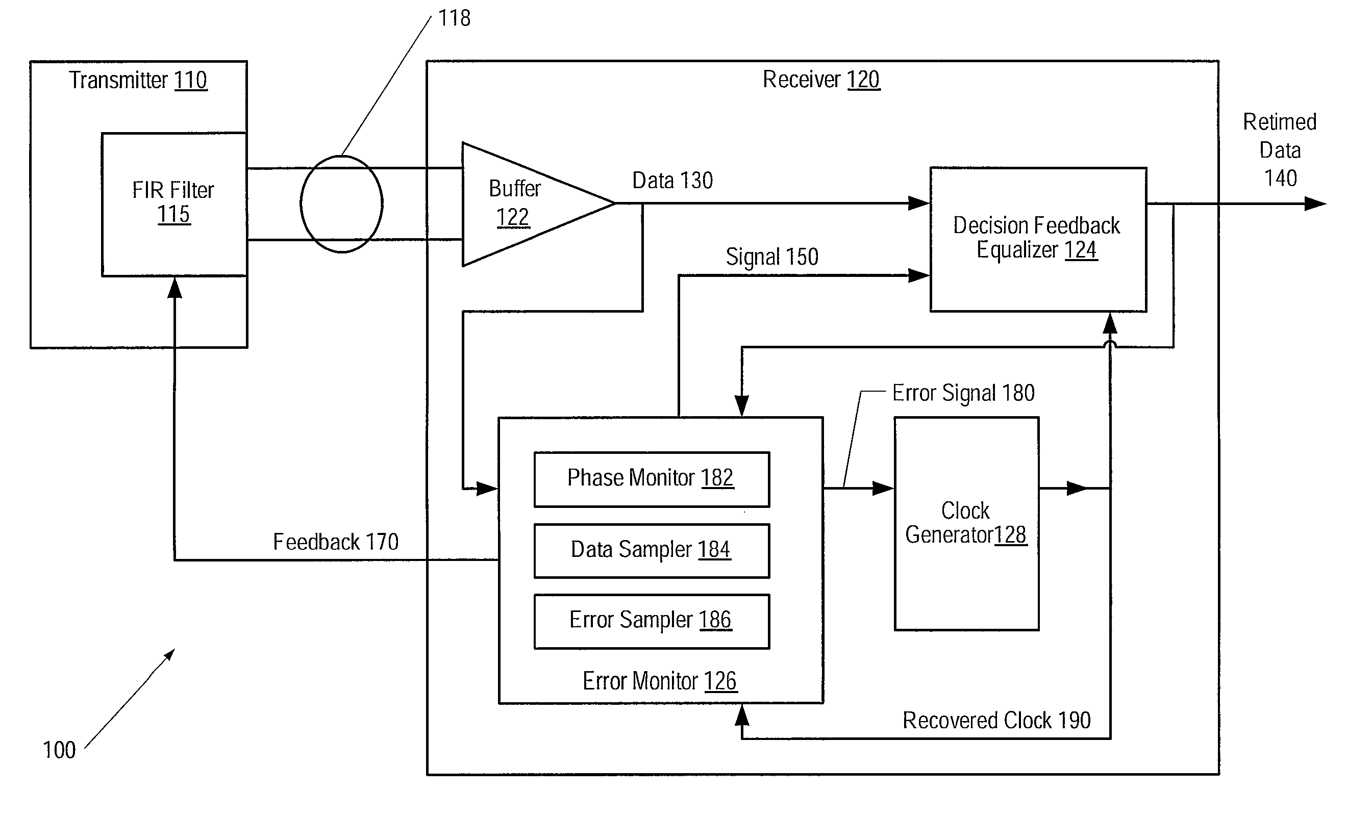
[0022]FIG. 1 is a generalized block diagram of one embodiment of a communications system 100. System 100 includes a transmitter 110 and a receiver 120 connected by a channel 118. In one embodiment, transmitter 110 and / or receiver 120 may form part of serializer-deserializer (SERDES) circuitry. In one embodiment, channel 118 may be a differential channel. Transmitter 110 may include a finite impulse response filter (FIR) 115 that may be used to equalize signals transmitted through channel 118. In one embodiment, receiver 120 may include a buffer 122, a decision feedback equalizer (DFE) 124, an error monitor 126, and a clock generator 128. Receiver 120 may generate a feedback 170 including one or more signals that are used to set values of parameters within filter 115. Various embodiments of filter 115 and receiver 120 are described below.

[0023]During operation, buffer 122 within receiver 120 may receive a data signal via channel 118. Buffer 122 may convert the received data signal to...


PUM


Abstract

A data communications system and methods are disclosed. The system includes a transmitter for conveying a data signal filtered by a finite impulse response (FIR) filter to a receiver via a channel. The receiver equalizes the received data signal using a decision feedback equalizer (DFE) and the FIR. The receiver samples the data signal to determine an error signal and uses the error signal to adapt settings of a pre-cursor tap coefficient of the FIR, one or more post-cursor tap coefficients of the FIR, a phase of the recovered clock, and a coefficient of the DFE. To adapt the settings, the receiver determines the error signal based on an error sample taken from the data signal in a single clock cycle. To determine an error signal, the receiver samples the data signal at a phase estimated to correspond to a peak amplitude of a pulse response of the channel.

Description

BACKGROUND OF THE INVENTION[0001]1. Field of the Invention[0002]This invention relates to clock and data recovery circuits and, more particularly, to techniques for clock and data recovery.[0003]2. Description of the Related Art[0004]High-speed data communication systems frequently rely on clock and data recovery (CDR) circuits within the receiver instead of transmitting a reference clock with the data. For example, serial data communications may include the use of serializer-deserializer (SERDES) elements at each end of a communications link. Within a SERDES, a CDR may extract a clock that is embedded in the incoming data stream. Once a clock is recovered, it is used to sample the incoming data stream to recover the individual bits. A variety of clock recovery circuits are well known, including phase-locked loops (both analog and digital) and delay lock loops. Regardless of the circuit used, a clock recovery circuit attempts to extract the frequency and phase of the clock from a da...

Claims


Application Information

Patent Timeline
Patent Type & Authority Applications(United States)
IPC IPC(8): H04L27/01
CPCH04L7/0337H04L2025/03503H04L25/03057
Inventor HUANG, DAWEIVAIRAVAN, MUTHUKUMARYOON, DONG JOONDOBLAR, DREW G.
Owner ORACLE INT CORP
Why Eureka
Try Eureka