Layer multiplying apparatus

a technology of multiplying apparatus and layer, which is applied in the direction of dough shaping, manufacturing tools, applications, etc., can solve the problems of more complex manufacturing, and achieve the effects of reducing shear stress, increasing shear stress in flowing mass, and constant cross-sectional areas

Inactive Publication Date: 2010-09-23
UNITED STATES OF AMERICA THE AS REPRESENTED BY THE SEC OF THE ARMY
View PDF24 Cites 28 Cited by
  • Summary
  • Abstract
  • Description
  • Claims
  • Application Information

AI Technical Summary

Benefits of technology

[0010]In a simple embodiment, only the intermediate section has open conduits, the housing sections having flat surfaces received against intermediate section. In this embodiment, the cross-sectional areas and change as the sub-streams move through the conduits, which changes flow rates increases shear stresses in the flowing mass. Since this can promote mixing under some rheological conditions, another embodiment of ISG according to the invention utilizes housing sections having open conduits which complement the open conduits in the intermediate section to form closed conduits having constant cross-sectional areas. This reduces shear stress in the layers, but is more complex to manufacture. However both housing sections are identical, as are the open conduits in opposite sides of the intermediate section, which simplifies manufacture.

Problems solved by technology

This reduces shear stress in the layers, but is more complex to manufacture.

Method used


Image

  • Layer multiplying apparatus
  • Layer multiplying apparatus
  • Layer multiplying apparatus

Examples


first embodiment

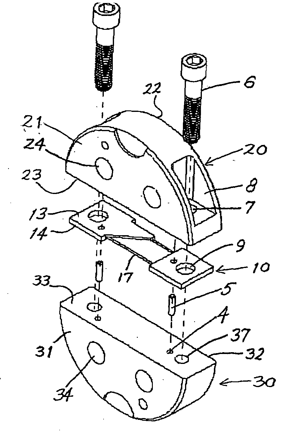
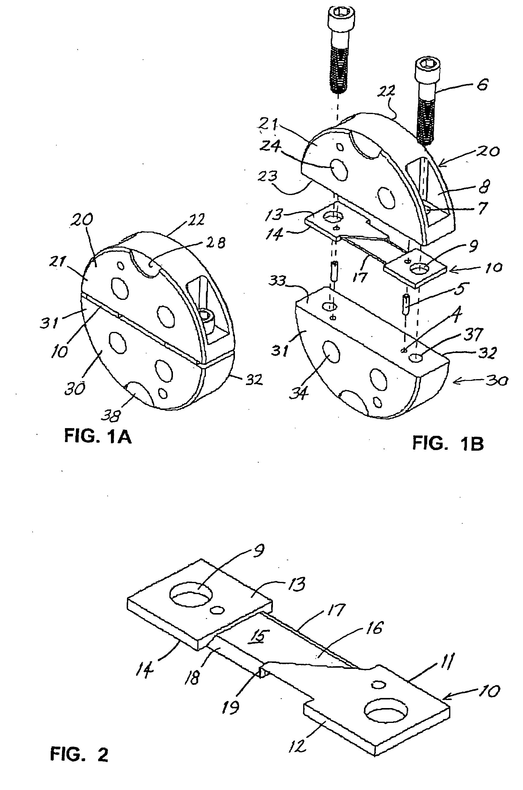
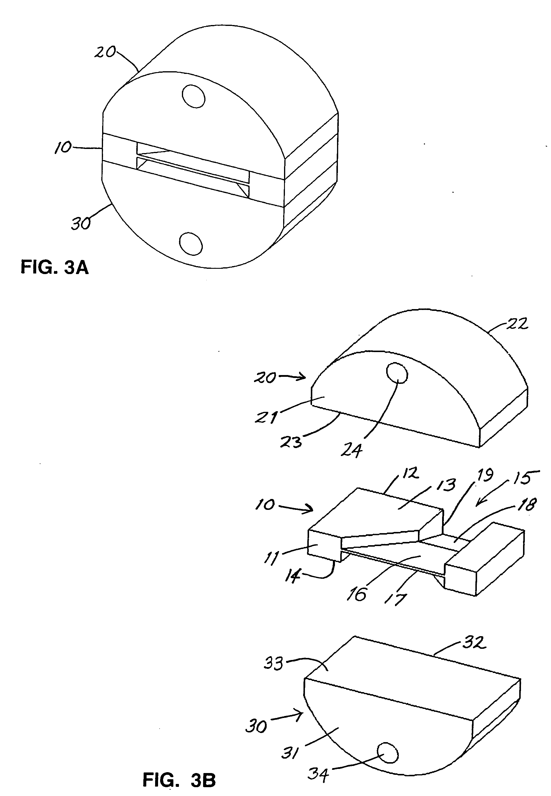
[0025]Referring to FIGS. 1A and 1B, ISG plate according to the invention includes an intermediate section 10, a top housing section 20, and a bottom housing section 30, the three basic parts being fixed together by screws 6, which are preferably socket head cap screws. Referring also to FIG. 2, the intermediate section 10 has oppositely facing first and second faces 11, 12, oppositely facing top and bottom faces 13, 14, and an open conduit 15 in each of the top and bottom faces 13, 14. Each open conduit 15 has a first stage 16 and a second stage 18, wherein the first stages 16 are separated by a first blade 17, which extends in an XZ plane, and the second stages 18 are separated by a second blade 19, which extends in a YZ plane. The first stages 16 contract in the X direction from the first face 11 toward respective second stages 18, and the second stages expand in the Y direction from respective first stages 16 to the second face 12.

[0026]The top and bottom housing sections 20, 30 ...

third embodiment

[0033]FIG. 6 is a perspective view of ISG according to the invention, wherein an intermediate section 40 is sandwiched between inner housing sections 60 and outer housing sections 70. The inner sections 60 are separate from the outer sections 70, so that the former can be replaced to obtain different conduit profiles. However each inner housing section 60 could also be designed as one piece with the respective outer housing section 70.

[0034]FIGS. 7A and 7B show the intermediate section 40 and the inner housing sections 60 in greater detail. Since the housing sections 60 are identical, no distinction will be made between the upper and lower sections in the following description.

[0035]The intermediate section 40 has oppositely first and second faces 41, 42, oppositely facing top and bottom faces 43, 44, and an open conduit 45 in each of the top and bottom faces 43, 44. Each open conduit has a first stage 46 and a second stage 48, wherein the first stages 46 are separated by a first bl...


PUM

PropertyMeasurementUnit
pressuresaaaaaaaaaa
widthaaaaaaaaaa
thicknessaaaaaaaaaa

Abstract

Apparatus for multiplying layers in a composite polymer stream includes an intermediate section having open conduits sandwiched between housing sections that close the conduits. The conduits have respective first stages separated by a first blade extending to a first face, and respective second stages separated by a second blade extending to a second face. The first stages separate the stream into sub-streams and compress and shift the sub-streams in a first dimension, whereas the second stages shift the sub-streams in a second dimension. In order to maintain a constant cross-sectional area of the sub-streams, the housing sections may be provided with complementary open channels. The apparatus can be used to multiply layers which are side-by-side or one-over-another by changing orientation in the direction of flow.

Description

BACKGROUND OF THE INVENTION[0001]1. Field of the Invention[0002]The present invention relates to an interfacial surface generator or ISG, and more particularly to an apparatus for dividing a composite polymer stream into sub-streams, followed by reshaping, repositioning, and recombining the sub-streams to produce a multi-layer laminate.[0003]2. Description of the Related Art[0004]U.S. Pat. No. 5,094,793 discloses an ISG utilizing a series of plates that are stacked in the Z-direction of an XYZ coordinate system, each plate having closed conduits machined therethrough in the Z direction. The first plate divides a composite polymer stream into a plurality of sub-streams arranged side-by-side in the X direction and repositions the sub-streams one over another in the Y direction; the second plate expands the sub-streams in the X direction; and the third plate compresses the sub-streams in the Y direction and combines them back into a stream having the same cross-section as the original ...

Claims


Application Information

Patent Timeline
Patent Type & Authority Applications(United States)
IPC IPC(8): B29C47/06
CPCB29C47/0019B29C47/0021B29C47/707B29C47/065B29C47/062B29C48/07B29C48/08B29C48/19B29C48/21B29C48/71
Inventor WINROTH, SCOTT ALLEN
Owner UNITED STATES OF AMERICA THE AS REPRESENTED BY THE SEC OF THE ARMY
Why Eureka
Try Eureka