Article Transport Facility

a technology for transporting facilities and articles, applied in conveyors, rope railways, routes, etc., can solve the problems of reducing the efficiency and capacity of article transporting, complication of configuration, and taking time to achieve the effect of improving the transporting capacity

Active Publication Date: 2010-09-30
DAIFUKU CO LTD
View PDF8 Cites 17 Cited by
  • Summary
  • Abstract
  • Description
  • Claims
  • Application Information

AI Technical Summary

Benefits of technology

[0010]With such a configuration, when transporting an article from an article transport location by a secondary path located on one side of the primary path to an article transport location by a secondary path located on the other side of the primary path, the article transport vehicle can, by traveling along the second connecting path, travel from the secondary path located on the one side of the primary path to the secondary path located on the other side of the primary path through the crossing portion with the primary path. This allows the article transport vehicles to travel from a secondary path located on the one side of the primary path to a secondary path located on the other side of the primary path without having to traveling along the primary path. Therefore, the article transport vehicles can transport an article from an article transport location by a secondary path located on one side o

Problems solved by technology

Therefore, the article transport vehicle would have to cover a long distance, reducing article transporting efficiency and capacity.
In the facility disclosed in the reference mentioned above, when transporting an article from an article transport location by the secondary path located on one side of the primary path to an article transport location by the secondary path located on the other side of the primary path, the article needs

Method used


Image

  • Article Transport Facility
  • Article Transport Facility
  • Article Transport Facility

Examples


Embodiment Construction

[0022]An embodiment of an article transport facility is described with reference to the attached drawings.

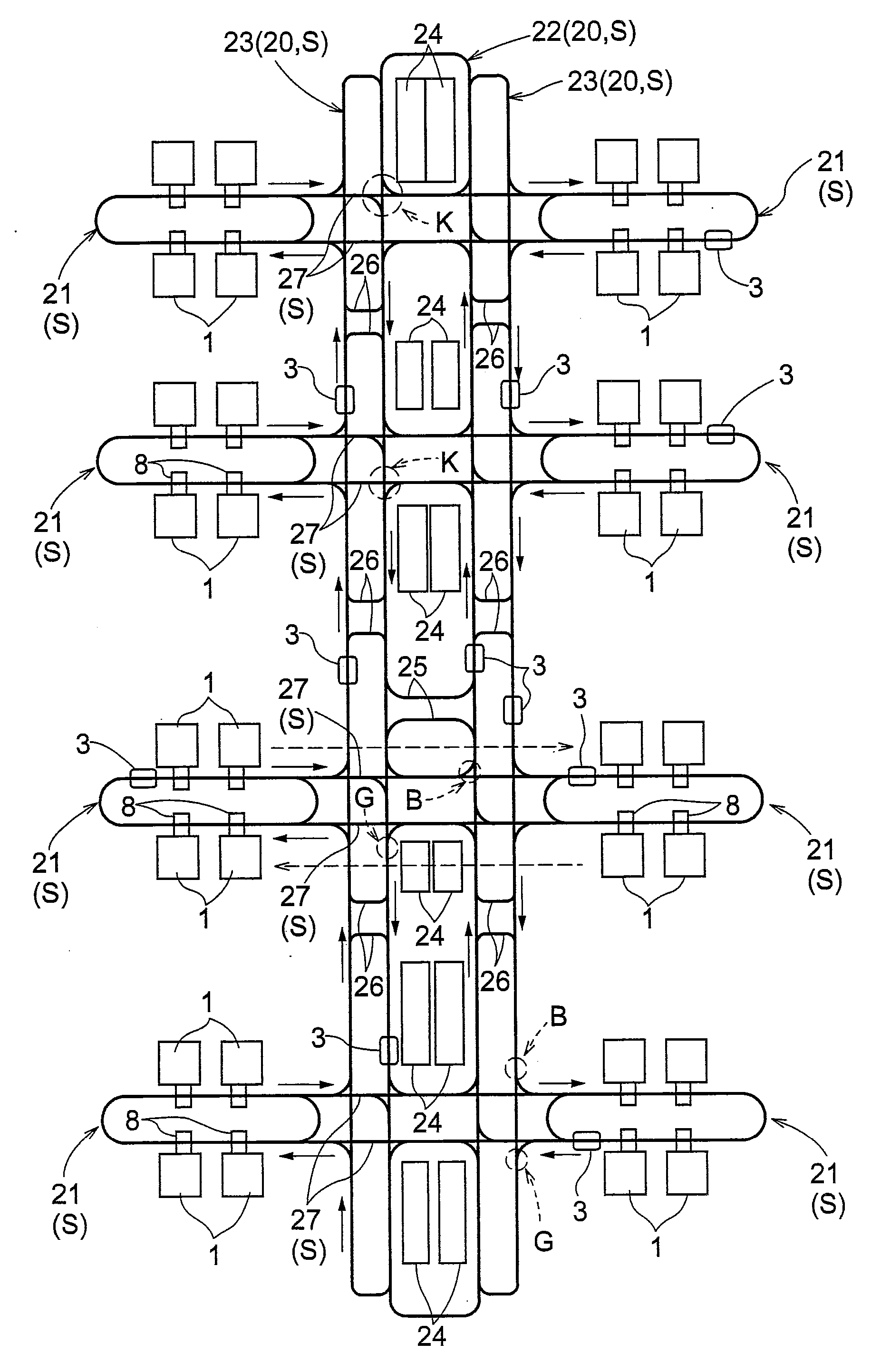
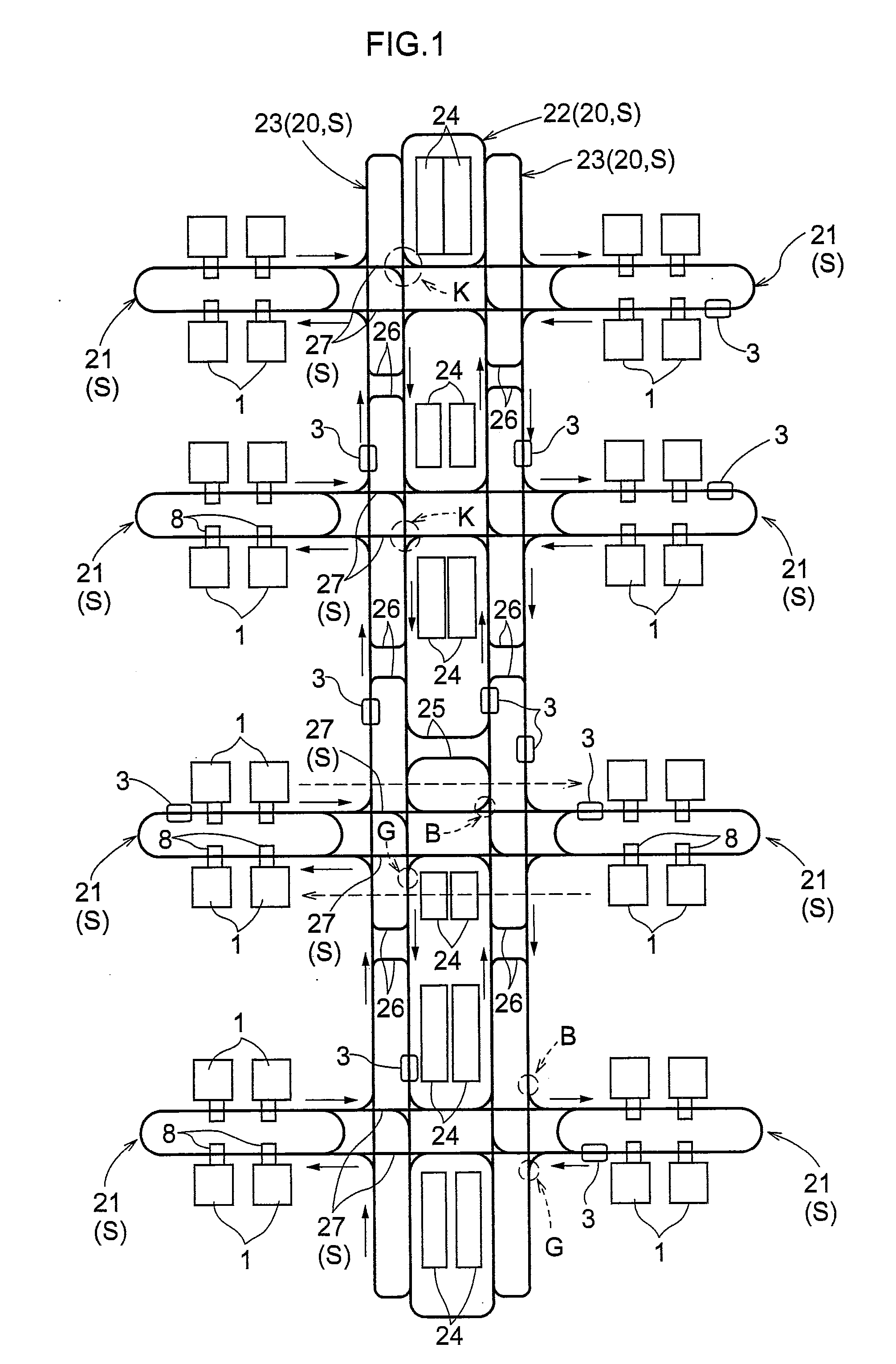
[0023]As shown in FIG. 1, the present article transport facility is provided with a plurality of article processors 1 for processing semiconductor substrates. Rails 2 are installed on the ceiling side, or to the ceiling, such that each of the rail 2 extends along and passes by these article processors 1 to form a travel path S. A plurality of article transport vehicles 3, of the type that is suspended from the ceiling and which can travel in one direction along a travel path 5, are provided. The article transport facility is configured such that the article transport vehicles 3 transport the articles 4 (i.e. containers for storing semiconductor substrates) among the plurality of article processors 1. Each rail 2 for the vehicles to travel on (travel rail for short) is fixedly installed to the ceiling with rail brackets 5 (see FIG. 2).

[0024]As shown in FIG. 2, each article transp...


PUM


Abstract

The article transport facility includes a plurality of article transport vehicles which can travel on a travel path defined by rails installed in the ceiling. The travel path includes a loop-shaped primary path, and secondary paths each arranged to extend along and by at least one article transport location, a first connecting path that connects the primary path and the secondary path, and a second connecting path, provided independently from the first connecting path, with one end portion connected to the secondary path located on one side of the primary path, and the other end portion connected to the secondary path located on the other side of the primary path.

Description

BACKGROUND OF THE INVENTION[0001]1. Field of the Invention[0002]The present invention relates to an article transport facility, and more specifically to an article transport facility including a plurality of article transport vehicles configured to travel along a travel path defined by one or more rails installed to the ceiling and wherein the travel path includes a primary path forming a loop and secondary paths, each arranged to extend by at least one article transport location, and a first connecting path connecting the primary path and a secondary path for allowing article transport vehicles to travel from the primary path to the secondary path and from the secondary path to the primary path, the secondary paths being located outside of the primary path and located on both one side and the other side of the primary path.[0003]2. Description of the Related Art[0004]In such an article transport facility, when an article transport location along the secondary path is specified as a...

Claims


Application Information

Patent Timeline
IPC IPC(8): E01B25/22
CPCB65G37/02B65G2201/0297H01L21/67715H01L21/67736H01L21/6773H01L21/67733H01L21/67727
Inventor OGURO, KEISUKEFUJITA, MOTOHIROTAKEMOTO, YUUYA
Owner DAIFUKU CO LTD
Why Eureka
Try Eureka